Linear multiple feeder for automatic surface-mounting device positioning apparatuses

a positioning apparatus and surface mounting technology, applied in the direction of instruments, apparatus for dispensing discrete objects, packaging goods, etc., can solve the problems of positioning repeatability, high production and operation costs, and the degree of slack must be allowed, so as to achieve the exposure of the desired electronic device with high precision, small and less expensive

Inactive Publication Date: 2010-03-23
L C M SRL
View PDF12 Cites 2 Cited by
  • Summary
  • Abstract
  • Description
  • Claims
  • Application Information

AI Technical Summary

Benefits of technology

[0009]Accordingly, it is an object of the present invention to provide a linear multiple feeder for an automatic surface mounted devices (SMD) positioning apparatus that enables highly precise exposure of the desired electronic devices or components for simultaneous pickup, thereby, ensuring that a plurality of pickup heads descend onto the feeder simultaneously so as to collect a selected number of suitably exposed and perfectly aligned SMDs.
[0010]Another object of the present invention is to provide a linear multiple feeder for an automatic surface mounting device positioning apparatus that is smaller and less expensive than comparable feeders of equivalent performance.
[0011]A further object of the present invention is to provide a linear multiple feeder e for an automatic surface mounting device positioning apparatus precision and reliability that are unaffected by an extraordinary number of operating cycles.
[0012]According to one aspect of the present invention, there is provided a linear multiple feeder for an automatic surface mounting device positioning apparatus. The device comprises a support structure, a plurality of reels of tape carrying the device rotatably mounted to the support structure, a member for retrieving a protective film detached from the tapes when the device or component is exposed for collection, a plurality of relatively parallel lanes on the support structure for delivering the tapes provided, downstream of the film-retrieving member, and a device for forward linear delivery of the tapes along the lanes. The apparatus comprises a carriage assembly moving alternately between two stops and carrying a row of tape-entraining pins selectively engageable with holes in the tape and inside the lanes so as to carry forward only those tapes selected. Respective elements are provided between the lanes for separating the film coating, drawn axially along by the film-retrieving member, in a direction opposite to that of delivery of the respective tape, in order to detach the film coating from the forward-moving tape, and force it against the separator elements. The tension created in the film coating by the film-retrieving member is suitable for biasing the separators against the bottom of their respective lanes and, thereby, preventing movement of those tapes that have not been selected for delivery, by locking them between the separators and the bottom of the lane.

Problems solved by technology

While gear wheel and linear delivery type feeder systems have been found useful, the highly complex configurations that are necessary to achieve high operating precision often makes these systems costly to produce and operate.
Gear wheel type feeder systems, in particular, have been found further disadvantageous in requirina that the wheel be able to engage tapes of different thicknesses about an arc of a circle, i.e., that some degree of slack must be allowed between the diameter of the tooth and a hole in the tape.
Frequently, however, this presents problems with positioning repeatability when different tapes are used.
Although helpful, this arrangement increases significantly the dimensions and structural complexity of the feeder, while failing to eliminate the risk of tape movement.
In addition, using this system, feeding the tapes has been found considerably more complicated.
Such system is also considered sensitive to any differences in the way the film is attached to the tape due to manufacturing defects or aging of the adhesive.

Method used


Image

  • Linear multiple feeder for automatic surface-mounting device positioning apparatuses
  • Linear multiple feeder for automatic surface-mounting device positioning apparatuses
  • Linear multiple feeder for automatic surface-mounting device positioning apparatuses

Examples


Embodiment Construction

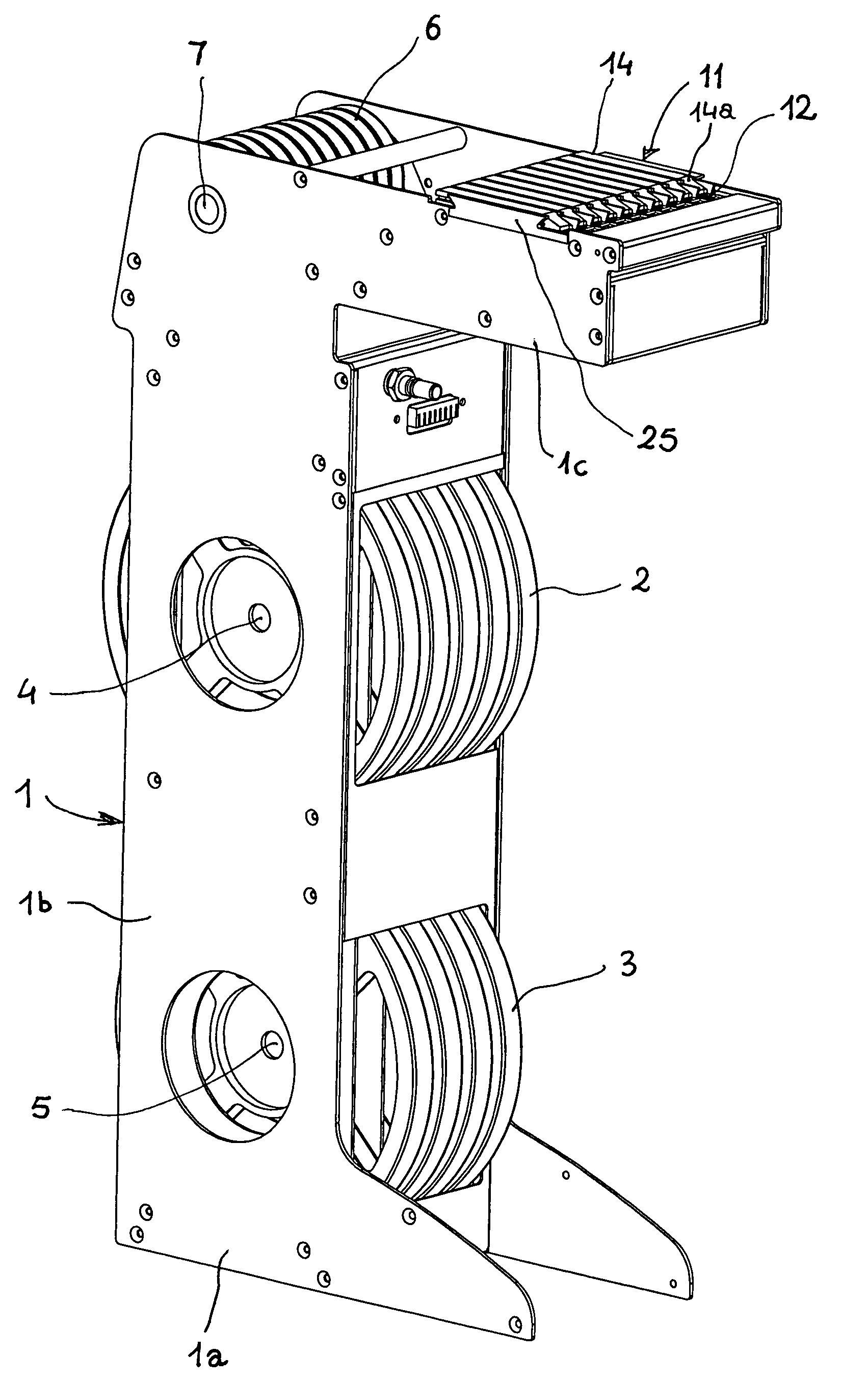
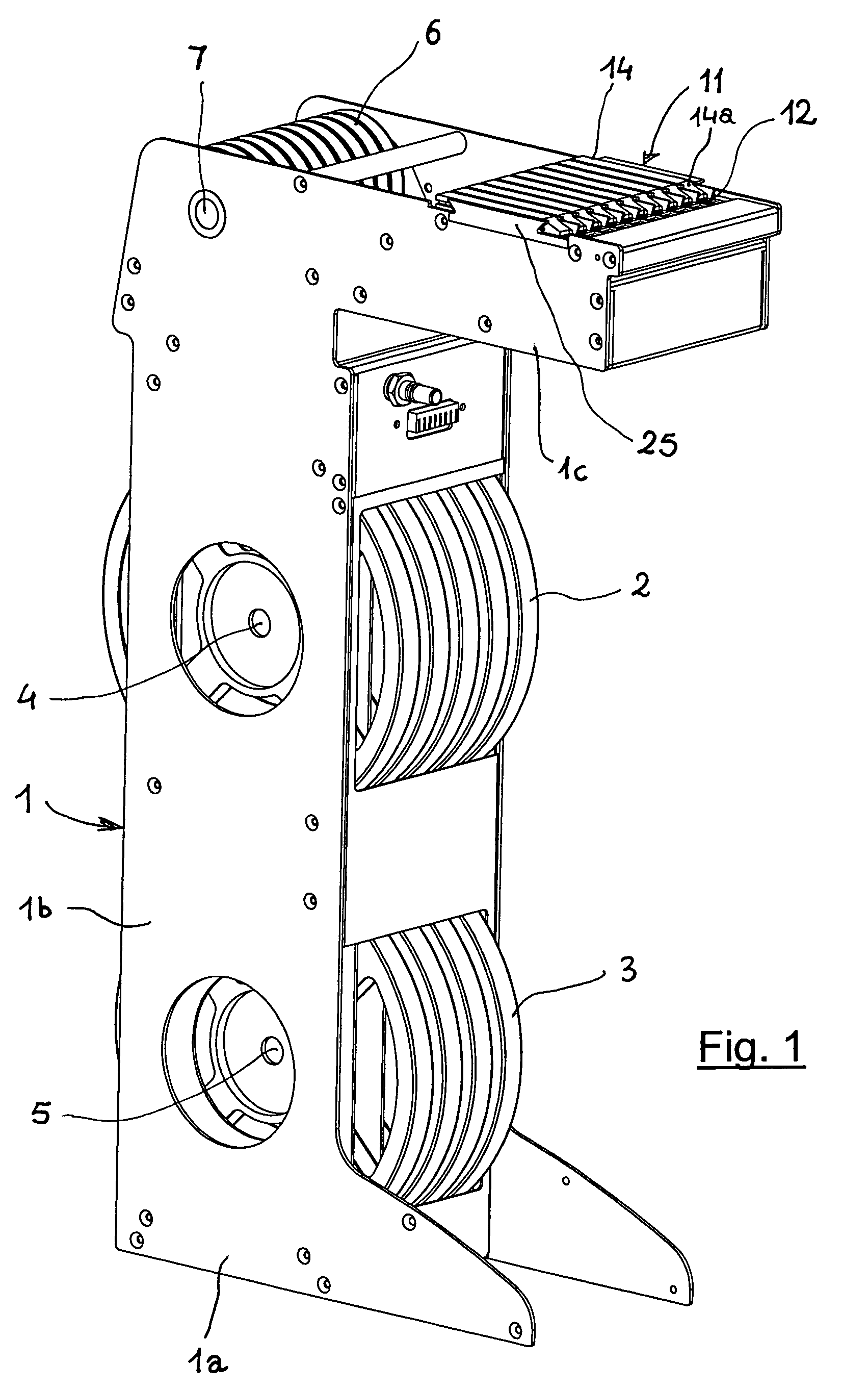
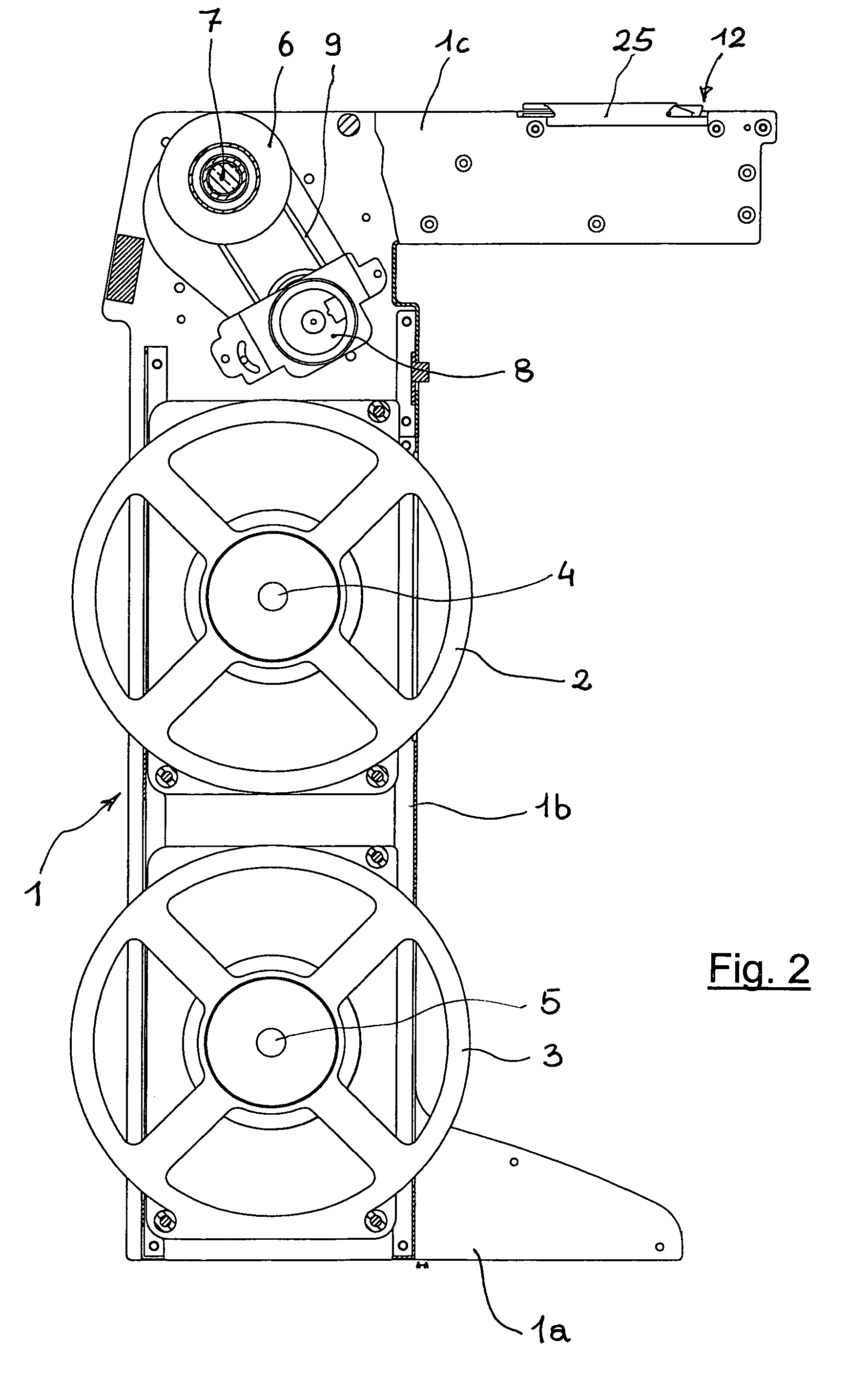
[0021]Referring now to the drawings and, more particularly, to FIGS. 1-6, there is shown generally a specific, illustrative linear multiple feeder for an automatic surface-mounting device (SMD) positioning apparatus, according to various aspects of the present invention. In one embodiment, illustrated in FIGS. 1-3, the feeder has a relatively rigid, box-like frame comprising a base portion 1a, an upright portion 1b rising from the base portion, and a top portion 1c extending generally horizontally from a free end of the upright portion. Inside upright portion 1b, reels 2, 3 are desirably mounted rotatably on respective spindles 4, 5 supported on either side, preferably at two different heights, by the upright portion. It is preferred that the reels be staggered relatively vertically so as to avoid any interference between tape(s) containing the SMD being unwound therefrom. At an upper end of upright portion 1b, generally at the same height as top portion 1c, a shaft 7 is provided on...


PUM

PropertyMeasurementUnit
tensionaaaaaaaaaa
tensile stressaaaaaaaaaa
forceaaaaaaaaaa

Abstract

A linear multiple feeder for use with an apparatus for automatically positioning surface-mounted devices (SMDs) collected from a tape wound on a reel. The tape has a protective film coating removably attached thereto, for enabling the device to be picked-up. The feeder comprises a support structure, a plurality of reels of tape carrying the device or component rotatably mounted to the structure, motor-driven wheels for retrieving the protective film being detached from the tape to expose those devices or components that are ready for collection, and a plurality of relatively parallel lanes on the support structure. Also provided is a device for forward linear delivery of the tape along the lanes. The lanes are provided with respective elements for separating the film coating entrained axially by the film-retrieving wheels in a direction opposite to that of delivery of the corresponding tape, thereby detaching the film coating from the tape as the latter moves forward.

Description

FIELD OF THE INVENTION[0001]The present invention relates generally to the production of electronic components and, more particularly, to surface-mounting technologies and the like.BACKGROUND OF THE INVENTION[0002]Conventional surface-mounting technologies, as are often used in the manufacture of electronic circuits, involve the use of surface mounted devices (SMDs) of increasingly limited dimensions. SMDs are typically installed using computer-controlled automatic “pick and place” type machines with one or more picking and placing heads, which collect the components from suitable feeders and deposit them in a selected position on a printed circuit board or the like.[0003]To prepare the surface mounted devices for collection from their packaging, feeders are often used. Briefly, the feeders open the packages and locate the devices or components at a position necessary for collection by a positioning head.[0004]Of the numerous packaging methods available today, the type most widely u...

Claims


Application Information

Patent Timeline
Patent Type & Authority Patents(United States)
IPC IPC(8): B32B38/10
CPCH05K13/0417Y10T428/14Y10T156/1994Y10T156/1174Y10T156/1195Y10T156/1956H05K13/0419
Inventor ARRIGHI, CLAUDIO
Owner L C M SRL
Why Eureka
Try Eureka