Protection of exposed contacts connected to a bridge rectifier against electrostatic discharge

a bridge rectifier and exposed contact technology, applied in emergency protective circuit arrangements, emergency protective arrangements for limiting excess voltage/current, etc., can solve problems such as damage to circuit components, electrostatic discharge is a common problem, etc., and achieve the effect of preventing damage to the diodes

Active Publication Date: 2009-07-30
FLI CHARGE LLC
View PDF12 Cites 11 Cited by
  • Summary
  • Abstract
  • Description
  • Claims
  • Application Information

AI Technical Summary

Benefits of technology

[0003]An embodiment of the present invention may therefore comprise a method of protecting a rectifier circuit from electrostatic pulses that occur between a power pad and an electronic device comprising: connecting a predetermined number of pairs of diodes in series in the same polarity direction to produce a plurality of series pairs of diodes; connecting the plurality of series pairs of diodes in parallel so that cathodes of one diode in each of the series pairs is connected to a positive power line and anodes of the other diode in each of the series pairs of diodes is connected to a negative power line; providing a predetermined number of contacts on the electronic device; connecting the predetermined number of contacts to input nodes located between the predetermined number of pairs of diodes; connecting a plurality of first bypass capacitors between the positive power line and the negative power line, proximate to each of the series pairs of diodes, to function as a bypass for the electrostatic pulses that have a rise time that allows the diodes to conduct and prevent damage to the diodes as a result of reverse biasing; connecting a plurality of second bypass capacitors between the input node and the negative power line, proximate to the input node, to discharge the electrostatic pulses, that have a rise time that is faster than the turn-on time of the diodes, to the negative power line.

Problems solved by technology

Electrostatic discharge (ESD) is a common problem for solid state circuits, such as circuits that use both discrete components and integrated silicon components.
These high energy discharges have been found to destroy circuit components if these circuit components are not properly protected.

Method used


Image

  • Protection of exposed contacts connected to a bridge rectifier against electrostatic discharge
  • Protection of exposed contacts connected to a bridge rectifier against electrostatic discharge
  • Protection of exposed contacts connected to a bridge rectifier against electrostatic discharge

Examples


Embodiment Construction

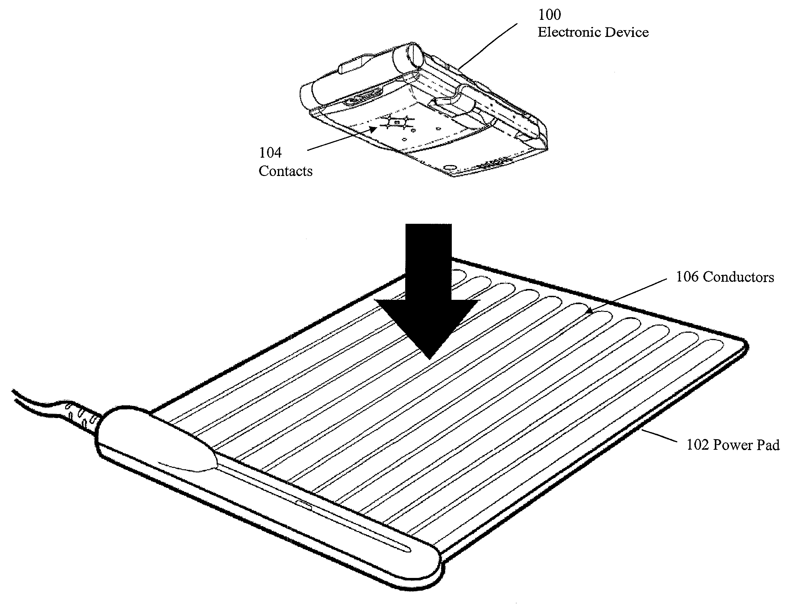
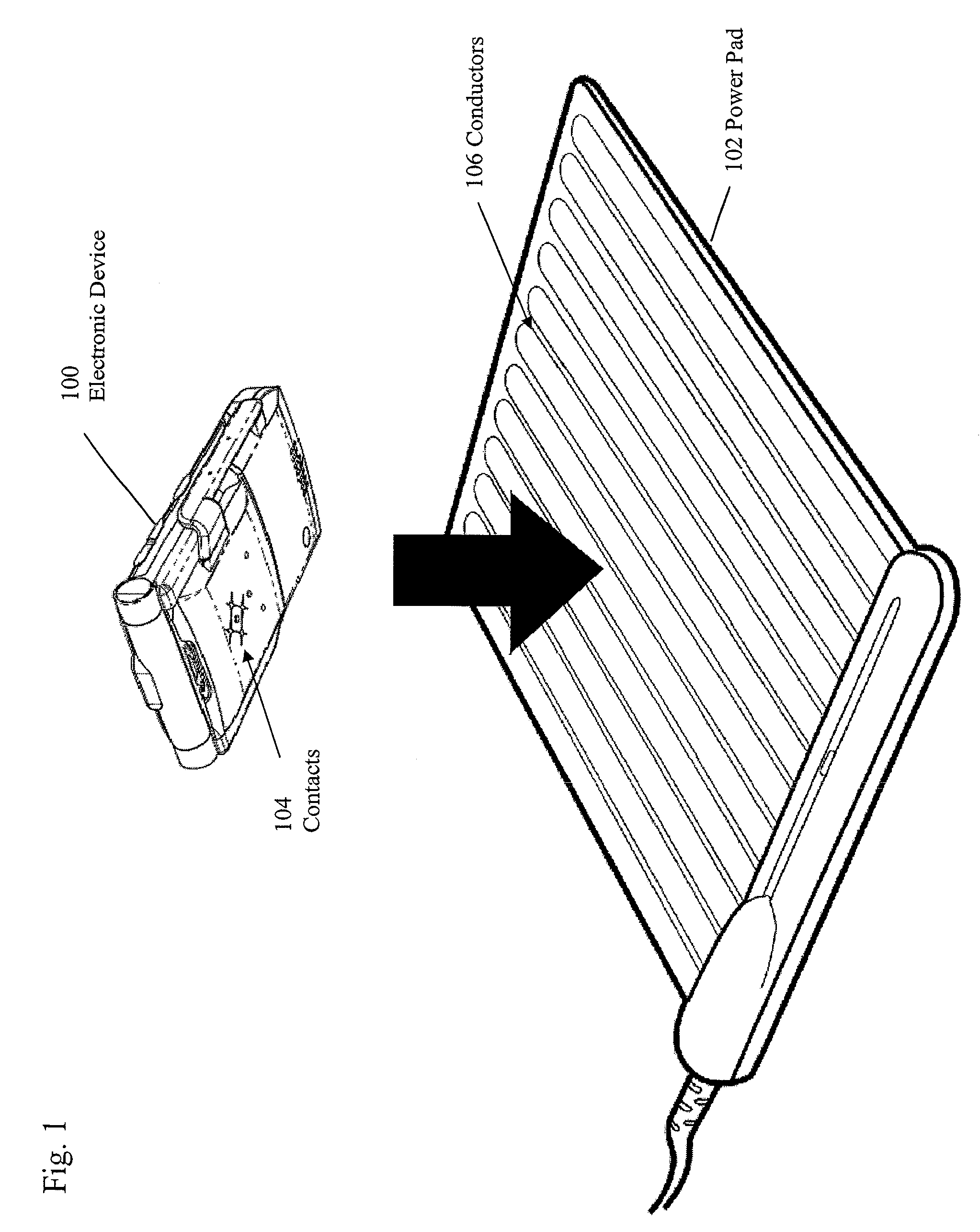
[0026]FIG. 1 is a schematic perspective view of a system for charging and / or providing power to an electronic device 100. As shown in FIG. 1, a power pad 102 contains a plurality of conductors for charging and / or providing power to the electronic device 100. Electronic device 100 can comprise devices such as cell phones, MP3 players, video players, smart phones, satellite phones, telematics devices, pagers, monitors, bar code scanners, GPS navigational devices, walkie talkies, personal digital assistants, and various types of computers, including portable computers, handheld computers, laptop computers, ultra-mobile computers, tablet computers, and various hybrid devices that combine one or more of these functions, or any portable electronic device, or other devices that can be charged, such as battery packs, capacitive devices, etc. Various features are more fully disclosed in U.S. patent application Ser. No. 11 / 672,010, filed Feb. 6, 2007, U.S. patent application Ser. No. 11 / 682,3...


PUM


Abstract

Disclosed is a protection circuit for protecting a rectifier circuit from electrostatic pulses. The circuit employs a first bypass capacitor that is connected between positive and negative power lines to bypass electrostatic pulses that have a rise time that allows the diodes to conduct and prevent damage to the diodes as a result of reverse biasing, and a second bypass capacitor that is connected between an input node and the negative power line to discharge the electrostatic pulses that have a rise time that is faster than the turn-on times of the diodes. Connection of the bypass capacitors at locations close to the rectifying diodes minimizes the effects of stray inductance that affects the operation of the rectifier circuit in response to fast rise time transient pulses.

Description

CROSS-REFERENCE TO RELATED APPLICATIONS[0001]This application is based upon and claims the benefit of U.S. provisional application Ser. No. 61 / 024,773, entitled “PROTECTING EXPOSED CONTACTS CONNECTED TO A BRIDGE RECTIFIER AGAINST ELECTROSTATIC DISCHARGE,” filed Jan. 30, 2008, the entire disclosure of which is herein specifically incorporated by reference for all that it discloses and teaches.BACKGROUND OF THE INVENTION[0002]Electrostatic discharge (ESD) is a common problem for solid state circuits, such as circuits that use both discrete components and integrated silicon components. Electrostatic discharges have extremely fast rise times of 1 ns or less. Peak currents can reach as high as 30 amps and unclamped voltages as high as 15 KV. These high energy discharges have been found to destroy circuit components if these circuit components are not properly protected.SUMMARY OF THE INVENTION[0003]An embodiment of the present invention may therefore comprise a method of protecting a rec...

Claims


Application Information

Patent Timeline
Patent Type & Authority Applications(United States)
IPC IPC(8): H02H9/04
CPCH02H7/1252
Inventor RANDALL, MITCH
Owner FLI CHARGE LLC
Why Eureka
Try Eureka