Switching regulator with boosted auxiliary winding supply

a technology of auxiliary winding supply and power supply, which is applied in the direction of electric variable regulation, process and machine control, instruments, etc., can solve the problems of impracticality or very inefficient in removing an internal low-voltage “auxiliary” power supply from the output or input of the converter, and achieve the effect of increasing the leakage inductance and increasing the operating voltag

Inactive Publication Date: 2009-07-30
CIRRUS LOGIC INC
View PDF103 Cites 37 Cited by
  • Summary
  • Abstract
  • Description
  • Claims
  • Application Information

AI Technical Summary

Benefits of technology

[0008]The above stated objective of providing operating voltage for control and / or other circuits powered by an auxiliary winding earlier in the start-up cycle of a switching converter is provided in a switching converter and a method of operation of the switching converter.
[0009]The switching converter has an inductive storage element including at least a primary and an auxiliary winding. The auxiliary winding is provided to a boost circuit that raises an available voltage of the auxiliary winding to a substantially higher voltage by actively switching an inductance, thereby providing the operating voltage for control and / or other circuits earlier in the start-up phase of the switching converter. The boost circuit may use the leakage inductance of the auxiliary winding, which may be wound to increase the leakage inductance, or an additional inductor may be used to provide an inductive storage element for the boost circuit.

Problems solved by technology

In order to supply power to control circuits of a switching power converter, an auxiliary winding is sometimes used, particularly at start-up when the voltage of the converter output has not risen sufficiently, or in implementations in which deriving an internal low-voltage “auxiliary” power supply from the output or input of the converter is impractical or very inefficient, e.g., in high-voltage input converters.
However, even an auxiliary winding-sourced power supply requires time for the filter capacitor or LC circuit that removes large AC variations from the auxiliary power supply output to charge to a sufficient voltage to operate the control circuits.

Method used


Image

  • Switching regulator with boosted auxiliary winding supply
  • Switching regulator with boosted auxiliary winding supply
  • Switching regulator with boosted auxiliary winding supply

Examples


Embodiment Construction

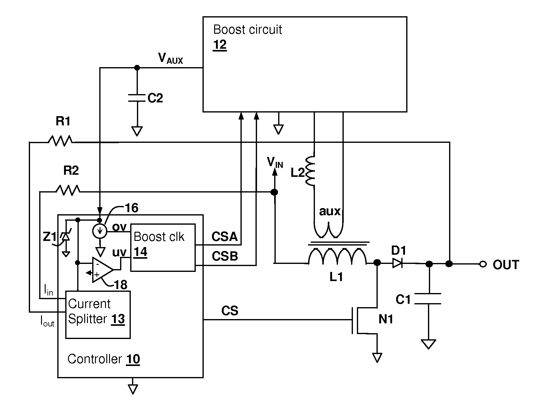
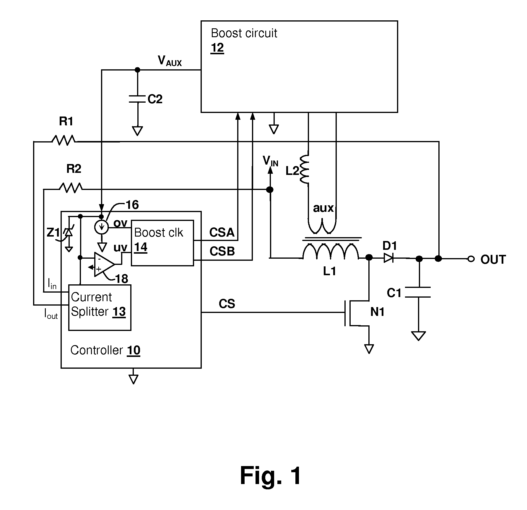
[0018]The present invention encompasses circuits and methods for providing power to control and / or other circuits internal to a switching power converter. The circuit operates from an auxiliary winding of the switching power converter and includes a boost circuit to boost the voltage available from the auxiliary winding, so that sufficient operating voltage for the control and / or other circuits is available earlier in the start-up phase of the switching power converter, than would otherwise be available from a passive rectifier / filter auxiliary power supply circuit.

[0019]Referring now to FIG. 1, a switching power converter in accordance with an embodiment of the present invention is shown. A switching controller 10 provides a switching control circuit CS that controls a switching circuit implemented by a transistor N1. When transistor N1 is active, an inductive storage element supplied by inductor L1 is charged by imposing input voltage VIN across inductor L1, causing a current thro...


PUM


Abstract

A boosted auxiliary winding power supply for a switched-power converter circuit provides operating voltage for control and other circuits early in the start-up phase of converter operation. A boost circuit has an input coupled to the auxiliary winding to boost the voltage available from the auxiliary winding at least during start-up of the switched-power converter. The boost thereby provides a voltage that is greater than the voltage across the auxiliary winding during start-up of the switched-power converter. The boost circuit may be actively switched at a rate higher than a switching rate of the switched-power converter, to increase a rate of rise of the operating voltage. Polarity information, which may be provided from the switched-power converter control circuit, can be used to actively rectify the output of the auxiliary winding.

Description

[0001]This application Claims priority under 35 U.S.C. §119(e) to U.S. Provisional Patent Application Ser. No. 61 / 024,583 filed on Jan. 30, 2008 and Ser. No. 61 / 083,717 filed on Jul. 25, 2008.BACKGROUND OF THE INVENTION[0002]1. Field of the Invention[0003]The present invention relates generally to switching power regulator circuits, and more specifically, to a switching power converter in which an auxiliary winding power supply includes a boost circuit to increase available voltage.[0004]2. Background of the Invention[0005]In order to supply power to control circuits of a switching power converter, an auxiliary winding is sometimes used, particularly at start-up when the voltage of the converter output has not risen sufficiently, or in implementations in which deriving an internal low-voltage “auxiliary” power supply from the output or input of the converter is impractical or very inefficient, e.g., in high-voltage input converters. Since the auxiliary power supply typically does no...

Claims


Application Information

Patent Timeline
Patent Type & Authority Applications(United States)
IPC IPC(8): H02M3/335
CPCH02M3/156Y10S323/901H02M2001/0006H02M1/0006
Inventor MELANSON, JOHN LGAETANO, MAURO L.THOMPSON, KARL
Owner CIRRUS LOGIC INC
Why Eureka
Try Eureka