Supercharge Your Innovation With Domain-Expert AI Agents!

Liquid jet head, method for manufacturing liquid jet head, and method for forming structure for liquid jet head

a liquid jet head and manufacturing method technology, applied in the direction of microlithography exposure apparatus, instruments, photomechanical treatment, etc., can solve the problems of difficult control of the manufacturing process increase in the length of the liquid jet head of the printer, and difficulty in making liquid jet heads, etc., to improve the reliability of the liquid jet head and the effect of high degree of automation

Active Publication Date: 2009-07-30
CANON KK
View PDF11 Cites 12 Cited by
  • Summary
  • Abstract
  • Description
  • Claims
  • Application Information

AI Technical Summary

Benefits of technology

The present invention provides a solution for the problems faced by conventional liquid jet recording heads by providing a highly reliable liquid jet head. This is achieved by improving the adhesion between the coating resin layer and the substrate of the liquid jet head using an adhesion improving layer. The coating resin layer includes a first resin material layer closest to the substrate and at least one second resin material layer, with the first resin material layer providing at least one stepped portion continuing from the periphery of the second resin material layer. This prevents the liquid passage plate of the liquid jet head from separating from the substrate, resulting in a more reliable liquid jet head. The manufacturing method in accordance with the present invention can even more precisely form a liquid jet head which is highly reliable in that its liquid passage plate is unlikely to separate from its substrate.

Problems solved by technology

However, increasing a printer in the number of ink ejection outlets results in the increase in the length of the liquid jet head of the printer.
However, it is rather difficult to control the manufacturing process for a liquid jet head so that the peripheral portions will have a specified thickness.
Thus, under certain conditions, it was rather difficult to make liquid jet heads, the liquid passage plate (resin layer) of which is sufficiently thin across its peripheral portions.

Method used


Image

  • Liquid jet head, method for manufacturing liquid jet head, and method for forming structure for liquid jet head
  • Liquid jet head, method for manufacturing liquid jet head, and method for forming structure for liquid jet head
  • Liquid jet head, method for manufacturing liquid jet head, and method for forming structure for liquid jet head

Examples


embodiment 1

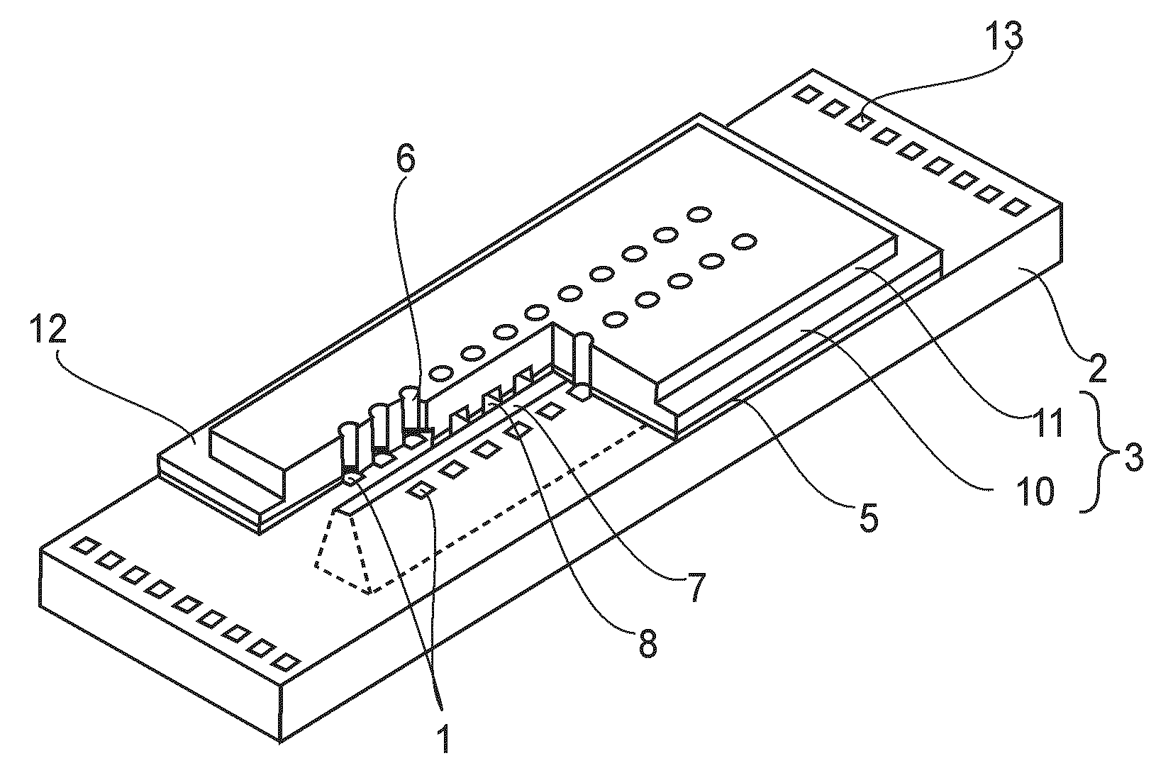
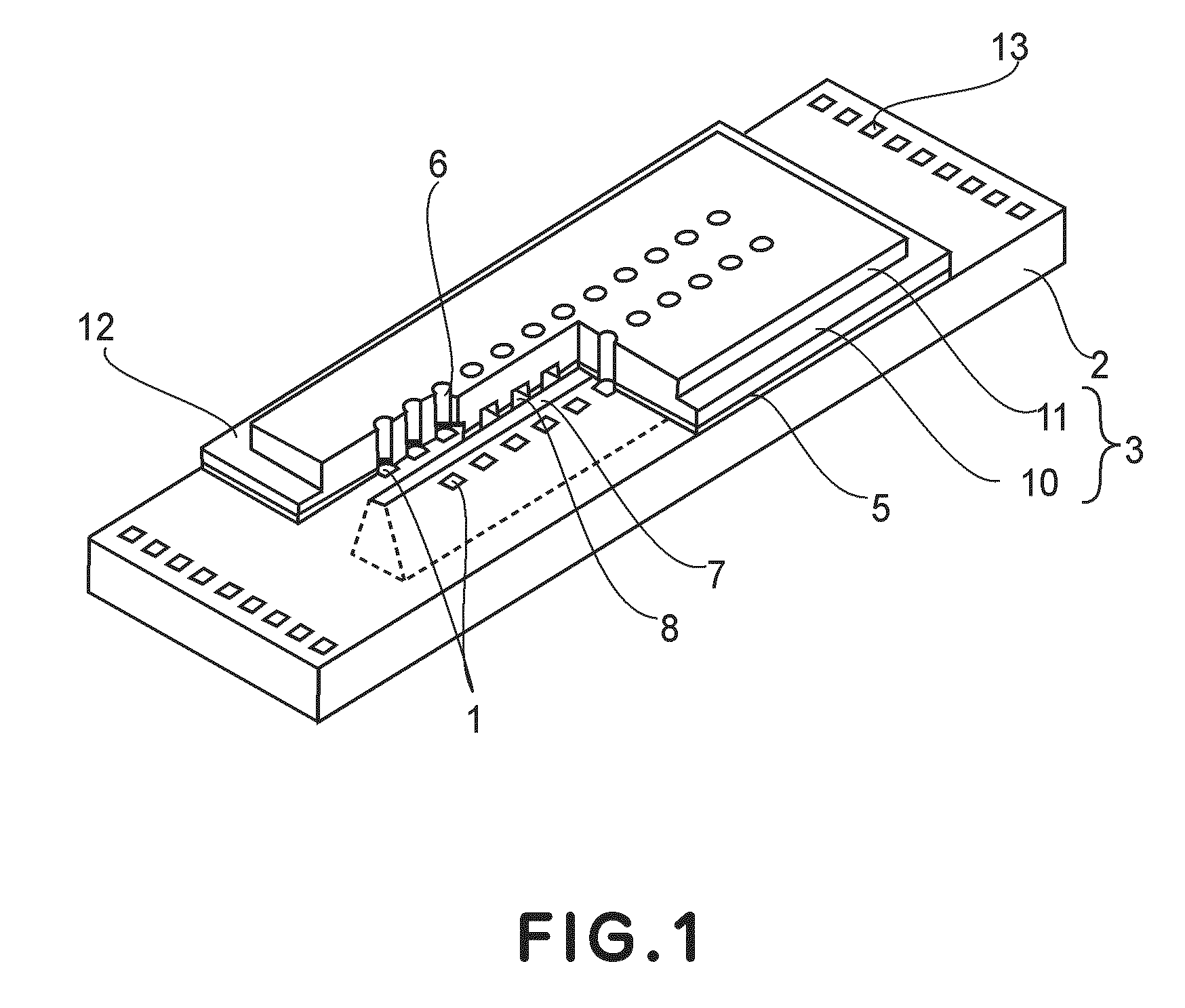
[0035]FIG. 1 is a schematic perspective view of the liquid jet head in this embodiment.

[0036]This liquid jet head is made up of a substrate 2, an ink passage plate 3, energy generating elements 1, contact pad 13. The energy generating elements 1 are disposed in two columns on the substrate 2, at a preset pitch. The contact pad 13 is for establishing electrical connection between the liquid jet head and the other devices, and is formed also on the substrate 2. The substrate 2 has an ink distribution hole 7, the top opening of which is between the two columns of energy generating elements. The ink passage plate 3 has two columns of ink ejection outlets 6, and multiple ink passages 8 which extend from the ink distribution hole 7 to the ink ejection outlets 6, one for one. The ink passage plate 3 hereafter may be referred to as a substrate covering resin layer 3, or simply as a resin layer 3. The ink passage plate 3 is bonded to the substrate 2 with the placement of an adhesion enhancem...

embodiment 2

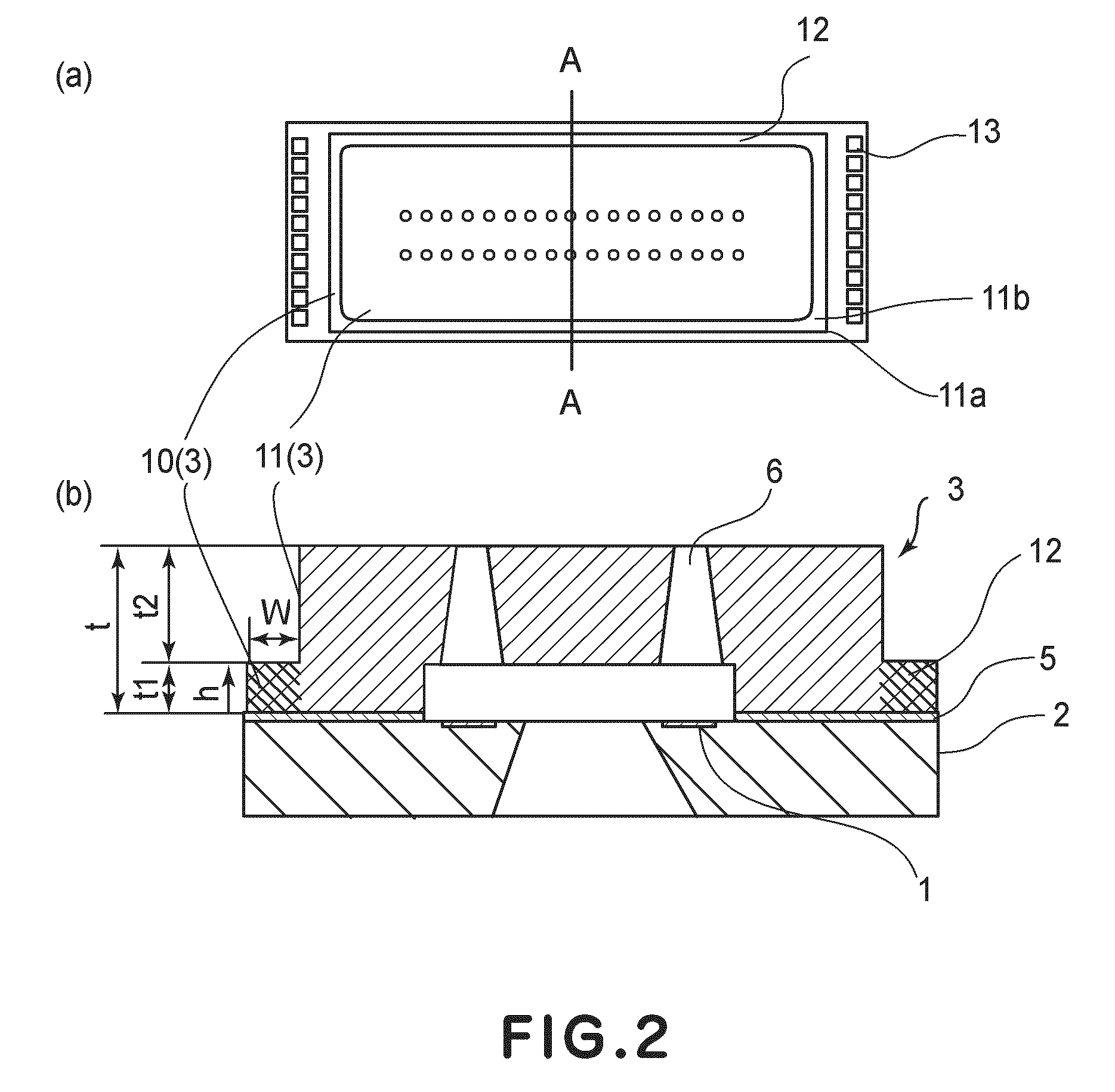
[0059]Next, referring to FIGS. 4(a) and 4(b), the second preferred embodiment of the present invention will be described. FIG. 4(a) is a top plan view of the recording chip, which is a part of the liquid jet head in this embodiment, and FIG. 4(b) is a sectional view of the recording chip, at a line A-A in FIG. 4(a).

[0060]In this embodiment, the second resin layer 11 is provided with a groove 9, which surrounds the ink passage portion having the liquid ejection outlets 6 and ink passages 8. The groove 9 is shaped so that the surface 9a of each of its two lateral walls is jagged; the cross section of the surface 9a of each of its lateral walls, at a plane perpendicular to the substrate 2, looks like saw teeth.

[0061]The structure of the liquid jet head in this embodiment is the same as that of the liquid jet head in the first embodiment, except that the second resin layer 11 of the latter has the groove 9. Thus, the features of the liquid jet head in this embodiment, which are the same...

embodiment 3

[0064]Next, the third preferred embodiment of the present invention will be described with reference to FIG. 5(a), which is a top plan view of the recording chip, that is, a part of the liquid jet head in this embodiment, and FIG. 5(b), which is a sectional view of the recording chip at a line A-A in FIG. 5(a).

[0065]Except that the liquid jet head in this embodiment is provided with a groove 19 and multiple connective portions 14, the liquid jet head in this embodiment is the same as that in the first embodiment. Thus, the features of the liquid jet head in this embodiment, which are the same as those of the liquid jet head in the first embodiment will not be described in detail. Further, the structural components of the liquid jet head in this embodiment, which are the same as the counterparts in the first embodiment, will be given the same referential codes as those given to the counterparts in the first embodiment, one for one, instead of directly describing them.

[0066]The liquid...


PUM

PropertyMeasurementUnit
thicknessaaaaaaaaaa
angleaaaaaaaaaa
thickness t1aaaaaaaaaa

Abstract

A liquid ejecting head including a coating resin layer including a plurality of ejection outlets for ejecting liquid and flow paths which are in fluid communication with the ejection outlets, respectively; an energy generating element for generating energy for ejecting liquid; and an adhesion improving layer provided between the coating resin layer and the substrate, wherein the coating resin layer further includes a first resin material layer closest to the substrate and at least one second resin material layer, and the first resin material layer provides at least one stepped portion continuing from a periphery of the second resin material layer.

Description

FIELD OF THE INVENTION AND RELATED ART[0001]The present invention relates to a liquid jet head which records by ejecting liquid toward recording medium. In particular, it relates to an ink jet recording head which records by ejecting ink. Further, it relates to a method for forming microscopic structural components usable for manufacturing semiconductors or the like.[0002]There have been disclosed various liquid jet heads of the so-called side shooter type, that is, liquid jet heads which jet ink droplets in the direction perpendicular to the substrate of a liquid jet head (Japanese Laid-open Patent Application 2007-261169).[0003]FIG. 6 is a schematic perspective view of an example of liquid jet head of the conventional side-shooter type. Incidentally, for simplification, FIG. 6 schematically shows a substantially smaller numbers of liquid ejection outlets 106 and energy generating elements 101 that the actual number of liquid ejection outlets 106 and energy generating elements 101 ...

Claims


Application Information

Patent Timeline
Patent Type & Authority Applications(United States)
IPC IPC(8): G03F7/20B41J2/16
CPCB41J2/14024B41J2/1603B41J2/1623B41J2/1645B41J2/1631B41J2/1632B41J2/1639B41J2/1629
Inventor MURAYAMA, HIROYUKITAGAWA, YOSHINORITAKEUCHI, SOUTAWATANABE, MAKOTOWATANABE, KEIJI
Owner CANON KK
Features
  • R&D
  • Intellectual Property
  • Life Sciences
  • Materials
  • Tech Scout
  • Unparalleled Data Quality
  • Higher Quality Content
  • 60% Fewer Hallucinations
Learn More