Surgical instruments and instrument handle having support brace

a technology of surgical instruments and handles, applied in the field of surgical instruments, can solve the problems of increasing the amount of force required, reducing the amount of power a doctor may comfortably be able to employ for retraction and/or distraction procedures, and requiring a sizable amount of force, so as to achieve the effect of reducing the angulation and rotation of the surgical instrumen

Inactive Publication Date: 2009-07-30
HAFFENREFFER MARK E
View PDF42 Cites 12 Cited by
  • Summary
  • Abstract
  • Description
  • Claims
  • Application Information

AI Technical Summary

Benefits of technology

[0008]According further to the system described herein, a method for performing a hip replacement procedure includes positioning a user's forearm in an instrument handle of a surgical instrument, the instrument handle including a grip, an extension arm a support brace that contacts the forearm. A first tool of the surgical instrument extends from the grip in a direction substantially perpendicular to the extension arm. Force is exerted on the surgical instrument in a direction substa...

Problems solved by technology

Retraction and distraction techniques involve the application of force to bone and/or tissue to exposure surgical areas and may require a sizable amount of force for an extended period of time.
The use of femoral head prostheses of larger sizes to reduce the changes of dislocation further increases the amount of force required since greater distraction of components is required.
Known retractor instruments used in orthopedic procedures often require the use of hand and wrist muscles to control angulation and rotation to reduce components into place during the surgery and thereby lessens the amount of power a doctor may comfortably be able to employ for retraction and/or distraction procedures.
In particular, the required control of ang...

Method used


Image

  • Surgical instruments and instrument handle having support brace
  • Surgical instruments and instrument handle having support brace
  • Surgical instruments and instrument handle having support brace

Examples


Embodiment Construction

[0022]Referring now to the figures of the drawings, the figures comprise a part of this specification and illustrate exemplary embodiments of the described system. It is to be understood that in some instances various aspects of the system may be shown schematically or may be exaggerated or altered to facilitate an understanding of the system.

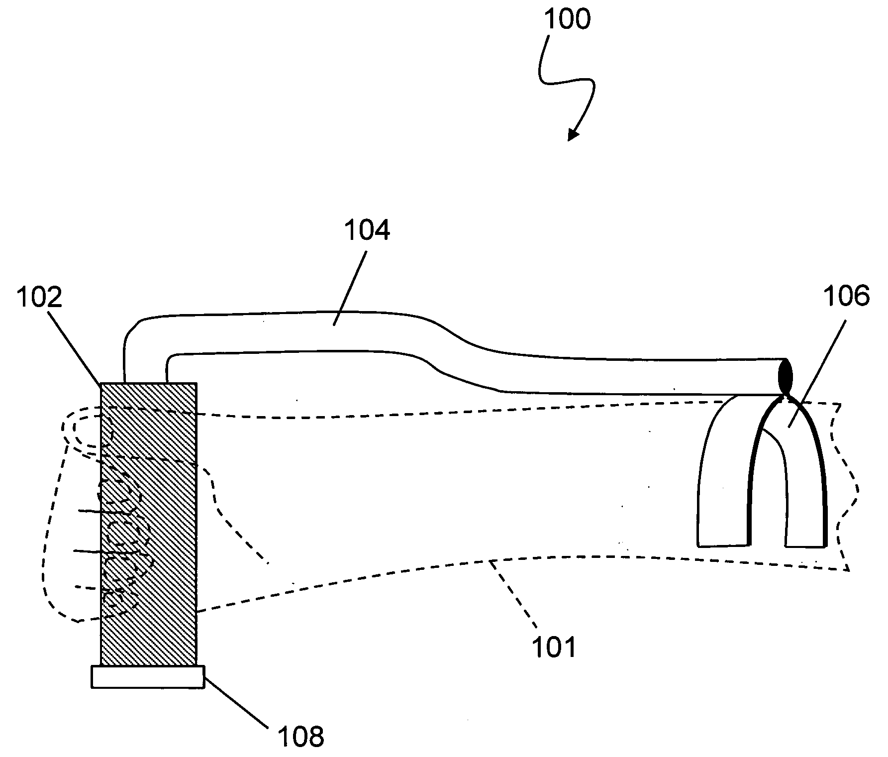
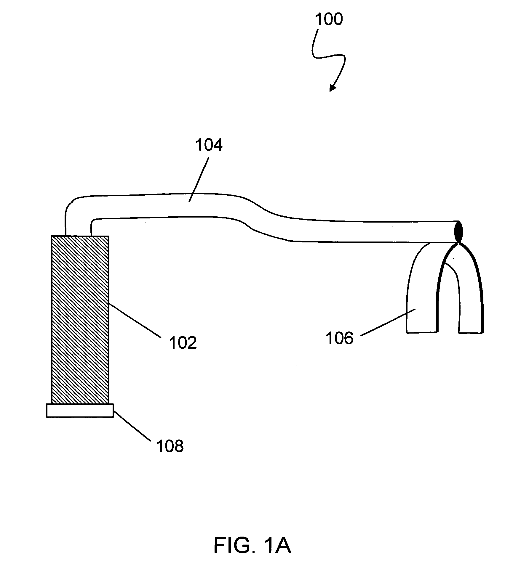
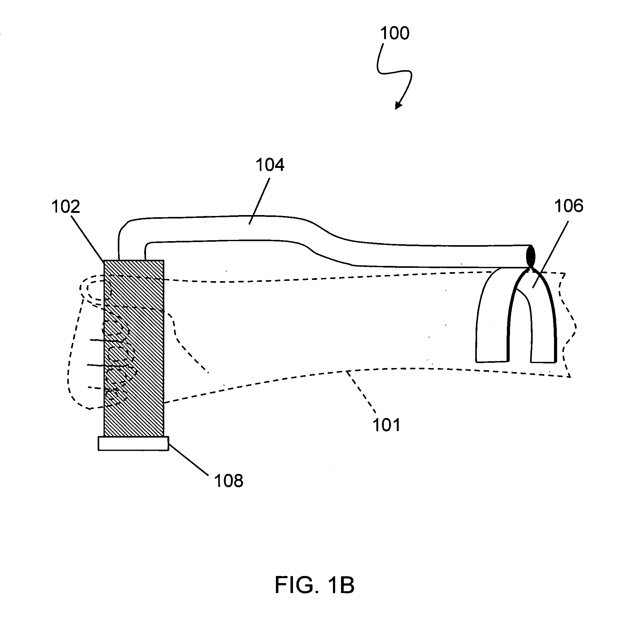
[0023]FIG. 1A is a schematic illustration of an instrument handle 100 according to an embodiment of the system described herein. The handle 100 includes a grip 102, an extension arm 104 attached to the grip 102 and a support brace 106 attached at the end of the extension arm 104. The end of the grip 102 may include a multiple-tool receptor 108, such as a bushing and / or other universal-type joint interface, that allows multiple tool components to be removably fitted therein. For example, the multiple-tool receptor 108 may include: a quick-connect mechanism in which a sleeve is pulled up to release the end and drops down to lock a tool into place...


PUM


Abstract

Orthopedic procedures, such as total hip replacement and/or other surgical procedures, involve the retraction and distraction of bone and tissue in order to reduce prosthesis components, such as a femoral head prosthesis, into place during surgery and to perform other surgical techniques, such as reaming of the acetabulum. An instrument handle that allows for enhanced control of surgical instruments and other tools that involve the application of directional force includes a grip, an extension arm and a support brace that is configured to contact a user's forearm during a surgical procedure. A multiple-tool receptor may also be included that allows for the removable and interchangeable use of tools in connection with the instrument handle. The system described herein allows for deep distraction without angulation using larger muscles or even one's body.

Description

TECHNICAL FIELD[0001]This application relates to the field of instruments and handles therefor, and more particularly to the field of surgical instruments.BACKGROUND OF THE INVENTION[0002]Orthopedic procedures, such as total hip replacement and / or other surgical procedures, involve the retraction and distraction of bone and tissue in order to reduce prosthesis components, such as a femoral head prosthesis, into place during surgery and to perform other surgical techniques, such as reaming of the acetabulum, which is the socket into which a femur head is disposed. Retraction and distraction techniques involve the application of force to bone and / or tissue to exposure surgical areas and may require a sizable amount of force for an extended period of time. The use of femoral head prostheses of larger sizes to reduce the changes of dislocation further increases the amount of force required since greater distraction of components is required.[0003]Known retractor instruments used in orth...

Claims


Application Information

Patent Timeline
IPC IPC(8): A61B17/56
CPCA61B17/02A61B17/8866A61B2019/261A61B2017/00464A61B2017/0275A61B2017/00442A61B90/53
Inventor HAFFENREFFER, MARK E.
Owner HAFFENREFFER MARK E
Why Eureka
Try Eureka