

Double-tube type stent
- Summary
- Abstract
- Description
- Claims
- Application Information
AI Technical Summary
Benefits of technology
Problems solved by technology
Method used
Image

Examples
Embodiment Construction
[0024]Reference will now be made in greater detail to a preferred embodiment of the invention, an example of which is illustrated in the accompanying drawings. Wherever possible, the same reference numerals will be used throughout the drawings and the description to refer to the same or like parts.
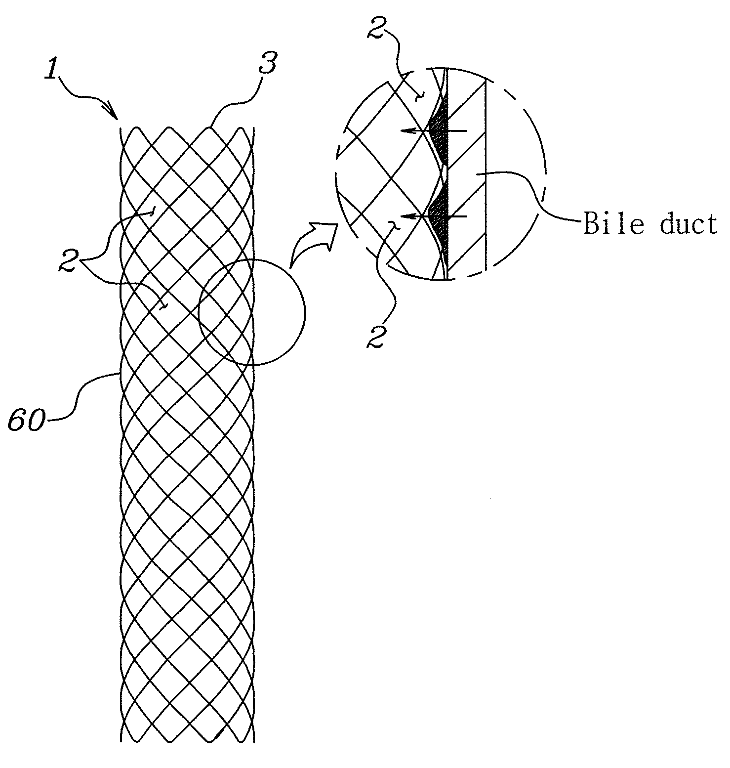
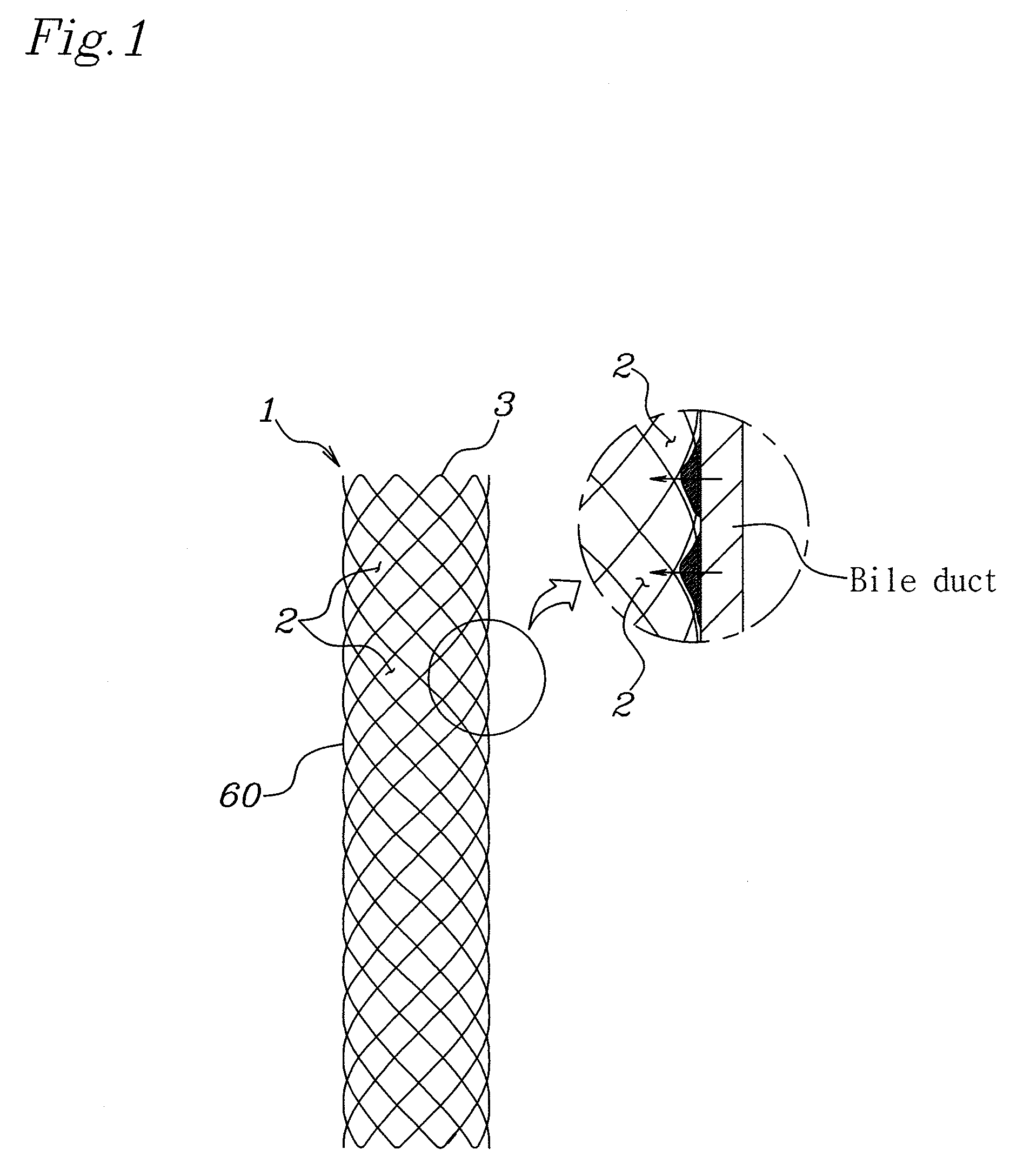
[0025]An embodiment of the present invention is characterized by a stent having a hollow cylindrical body that has a plurality of rhombic spaces formed by weaving a superelastic shape-memory-alloy wire so as to be crossed.
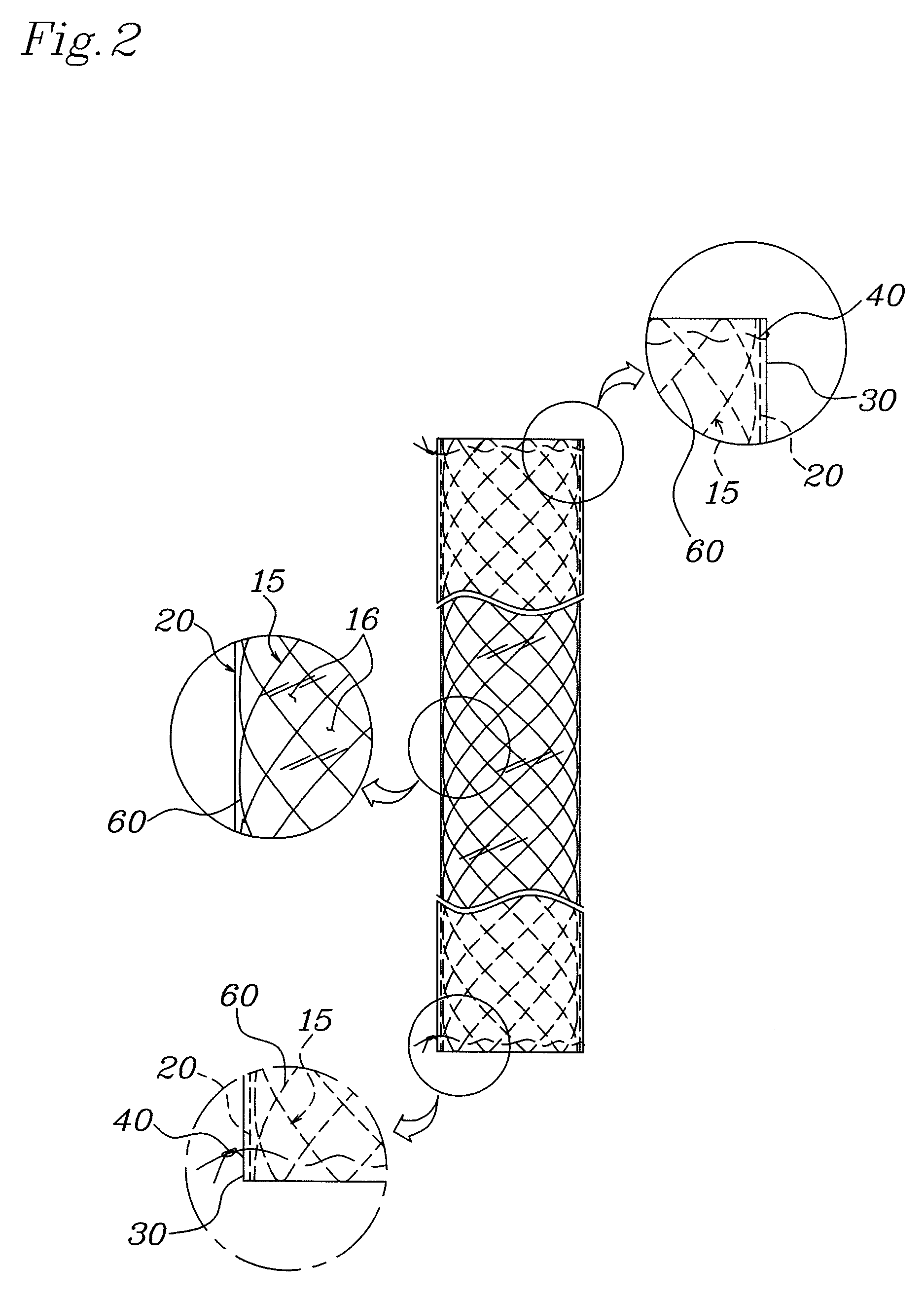
[0026]As illustrated in FIGS. 2, 3 and 4, according to an embodiment of the present invention, a double-tube type stent has a hollow cylindrical body 15, which has a plurality of rhombic spaces 16 formed by weaving a superelastic shape memory alloy wire 60 so as to be crossed and which is coated with a thin film on an outer surface thereof.
[0027]At this time, the thin film includes a silicon coating layer 20 formed by immersing the cylindrical body 15 into a silicon solut...
PUM
| Property | Measurement | Unit |
|---|---|---|
| Superelasticity | aaaaa | aaaaa |
Abstract
Description
Claims
Application Information