Measurement tool and method of use

a technology of measurement tool and measurement method, which is applied in the direction of instruments, specific gravity measurement, and well accessories, etc., can solve the problems of invalidating subsequent tests, difficulty in bringing fluid to the surface from particular wells, and less practicability

Active Publication Date: 2009-08-06
WEATHERFORD TECH HLDG LLC
View PDF9 Cites 17 Cited by
  • Summary
  • Abstract
  • Description
  • Claims
  • Application Information

AI Technical Summary

Benefits of technology

[0036]Alternatively, the signal generator can energise the pipe to oscillate close to or at its resonant frequency, and then the excitation can be stopped and the decaying oscillations observed. The pipe will oscillate at its resonant frequency during this decay, and it is recognised that the decay is exponential with a characteristic decay curve time constant which is inversely related to the spectrum line width that could otherwise be measured. Accordingly, measuring the decay curve can provide information about the spectrum for use in the viscosity (and perhaps also density) measurements.
[0054]The measurement tool according to all of its aspects has additional benefits in multi-flow formation testing tools such as that described in U.S. patent application Ser. No. 11 / 626,461 filed on 24 Jan. 2007. In this formation testing tool two (or more) fluid flows from the formation are kept separate and are tested separately, and a measurement tool of the present invention could be arranged in each flow line and direct comparisons between the two fluids could be made as desired. Where one flow line recovers fluid from the formation surrounding the path of the fluid recovered through the other flow line, the comparison can assist in determining when virgin fluid is being recovered and the volume of formation from which recovery is taking place.

Problems solved by technology

This practice has become less desirable primarily because of the harmful environmental impact of needing to flare-off excess fluid.
Also, there is difficulty in bringing the fluid to the surface from particular boreholes, especially sub-sea boreholes.
Furthermore, the pressure and temperature of the fluid changes during its movement to the surface, and these pressure and temperature changes can cause changes in the consistency of the fluid (i.e. the fluid may separate out or otherwise change its material characteristics) which may invalidate the subsequent test.

Method used


Image

  • Measurement tool and method of use
  • Measurement tool and method of use
  • Measurement tool and method of use

Examples


Embodiment Construction

[0055]The invention will now be described in more detail, by way of example, with reference to the accompanying drawings, in which:

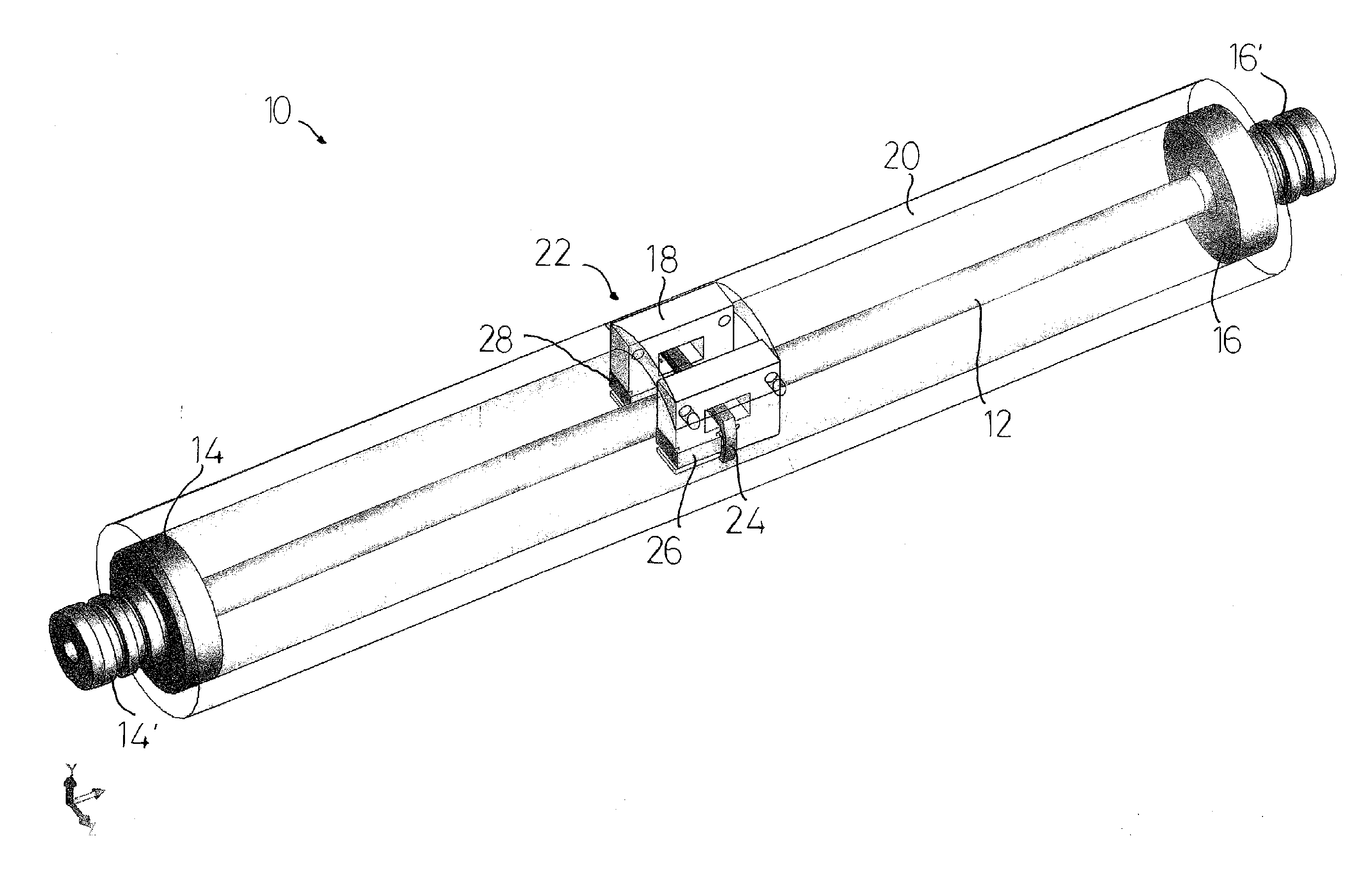
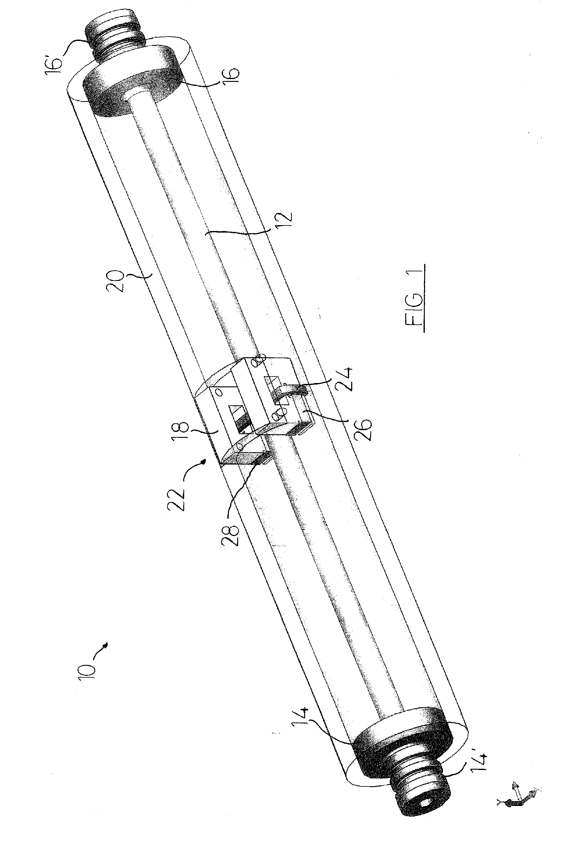
[0056]FIG. 1 shows a perspective view of one embodiment of measurement tool according to the invention;

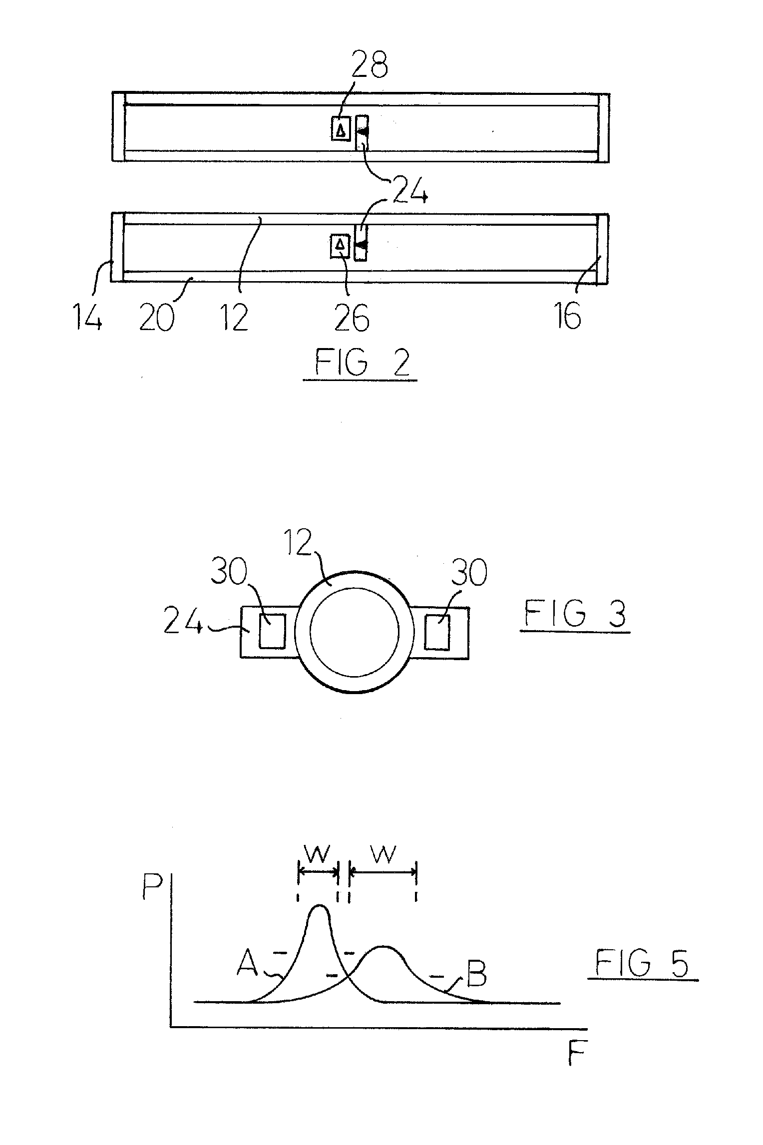
[0057]FIG. 2 shows a side view of part of another embodiment of measurement tool according to the invention;

[0058]FIG. 3 shows an end view of the yoke and pipe of the measurement tool of FIG. 2;

[0059]FIG. 4 shows an electrical circuit suitable for exciting oscillations in the pipe;

[0060]FIG. 5 shows a representation of two spectra for the oscillations in a pipe of a tool such as that of FIG. 1 or FIG. 2;

[0061]FIG. 6 shows two curves representing measurements upon the spectra of FIG. 5;

[0062]FIG. 7 shows two curves representing the effect of adding a mass upon the resonant frequencies of the oscillation of a pipe;

[0063]FIG. 8 shows a magnet and coil arrangement for an alternative exciter;

[0064]FIG. 9 shows an exciter using two of the magnet and coil arra...


PUM

PropertyMeasurementUnit
viscosityaaaaaaaaaa
densityaaaaaaaaaa
lengthaaaaaaaaaa

Abstract

This invention relates to a measurement tool, and in particular to a measurement tool for use in determining the density and / or viscosity of a stationary or moving fluid. The measurement tool has been designed for use in borehole applications during the location and exploitation of oil and gas reserves. The measurement tool has a resilient pipe with a substantially uniform cross-section along its length, and the fluid is located within the pipe. The pipe carries an exciter which is connected to a signal generator, the exciter and signal generator being adapted to impart transverse and / or rotational oscillations to the pipe. Measuring the frequency of the oscillations can be used to determine the density and / or the viscosity of the fluid within the pipe.

Description

CROSS REFERENCE TO RELATED APPLICATION[0001]This application claims priority from Great Britain Application No. 0725199.4, filed Dec. 22, 2007, which is also incorporated herein by reference.FIELD OF THE INVENTION[0002]This invention relates to a measurement tool, and in particular to a measurement tool for use in determining a parameter of a stationary or moving fluid. The measurement tool has been designed for use in borehole formation testing and the following description will therefore relate primarily to such applications, but the invention is not thereby limited.BACKGROUND OF THE INVENTION[0003]Measurement tools are in widespread use in borehole formation testing, for example in boreholes drilled into the earth in order to test for or recover underground reserves of oil and / or gas. Some such tools are carried by the drill string and the measurements are carried out during the borehole drilling operation (so-called “measurement-while-drilling” (MWD) or “logging-while-drilling” ...

Claims


Application Information

Patent Timeline
Patent Type & Authority Applications(United States)
IPC IPC(8): G01N11/00G01N9/00
CPCE21B49/08G01N2011/006G01N11/162G01N9/002G01N11/00E21B49/082G01N2009/006
Inventor WAID, MARGARET COWSARKASPERSKI, BRYAN W.YURATICH, MICHAEL ANDREW
Owner WEATHERFORD TECH HLDG LLC
Why Eureka
Try Eureka