Cooler device

a cooling device and cooling chamber technology, applied in indirect heat exchangers, lighting and heating apparatus, instruments, etc., can solve the problems of nickel chemical-plating process not meeting environmental protection requirements, high manufacturing cost, low yield rate, etc., and achieve the effect of quick dissipation

Inactive Publication Date: 2009-08-06
HUANG TSUNG HSIEN
View PDF18 Cites 37 Cited by
  • Summary
  • Abstract
  • Description
  • Claims
  • Application Information

AI Technical Summary

Benefits of technology

[0006]The present invention has been accomplished under the circumstances in view. According to one aspect of the present invention, the cooler device comprises a base panel, a radiation fin module, and one or more U-shaped heat pipes. The base panel has multiple mounting grooves on the top wall, and multiple locating grooves on the bottom wall. The radiation fin module is formed of a stack of radiation fins. Each radiation fin has multiple mounting through holes, and a root portion that is respectively riveted to the mounting grooves of the base panel. Each U-shaped heat pipe has a first extension arm respectively and tightly fitted into the mounting through holes of the radiation fins, and a second extension arm respectively and tightly fitted into the locating groove of the base panel. The second extension arm of each U-shaped heat pipe has a flat bottom wall kept in flush with the bottom wall of the base panel for direct contact with the hot side of a semiconductor electronic device or the like to transfer heat energy from the semiconductor electronic device to the radiation fins efficiently for quick dissipation.
[0007]According to another aspect of the present invention, the second extension arm of each U-shaped heat pipe has a cross section fitting the cross section of the locating grooves on the bottom wall of the base panel. After the second extension arms of the U-shaped heat pipes are fitted into the locating grooves of the base panel, the U-shaped heat pipes and the base panel are squeezed, thereby enhancing the connection tightness between the base panel and the U-shaped heat pipes and flattening the bottom wall of the second extension arm of each U-shaped heat pipe.
[0008]According to another aspect of the present invention, the U-shaped heat pipes are fastened to the radiation fins of the radiation fin module and the base panel by means of tight fitting. When the cooler device expands with heat, the tightness of the connection of the component parts of the cooler device is enhanced, thereby enhancing the heat dissipation efficiency. Further, because the cooler device does not require any soldering or electroplating process, the fabrication of the cooler device satisfies the requirements of environmental protection and does not cause any pollution.

Problems solved by technology

This fabrication procedure is complicated, resulting in a high manufacturing cost and low yield rate.
The nickel chemical-plating process does not satisfy the requirements of environmental protection.
However, because the heat transfer coefficient (K value) of the aluminum or copper base panel is smaller than the heat pipes and because the heat pipes are not kept in direct contact with the hot side of the semiconductor electronic device, the heat transfer efficiency of this design of cooler device is not excellent.

Method used


Image

  • Cooler device
  • Cooler device
  • Cooler device

Examples


Embodiment Construction

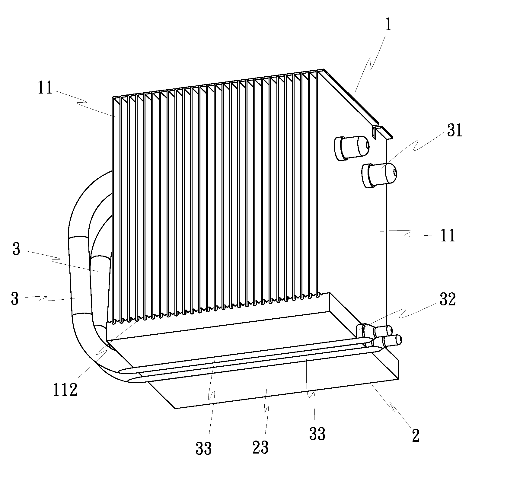
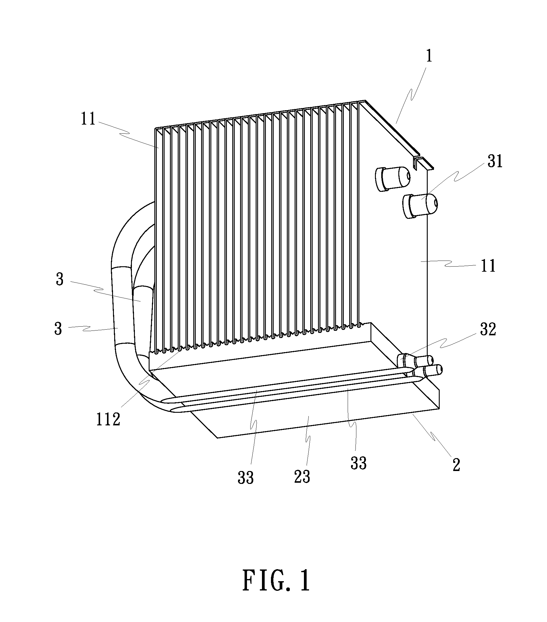
[0021]FIGS. 1˜3 show a cooler device in accordance with a first embodiment of the present invention, which comprises a radiation fin module 1, a base panel 2, and at last one, for example, two heat pipes 3.

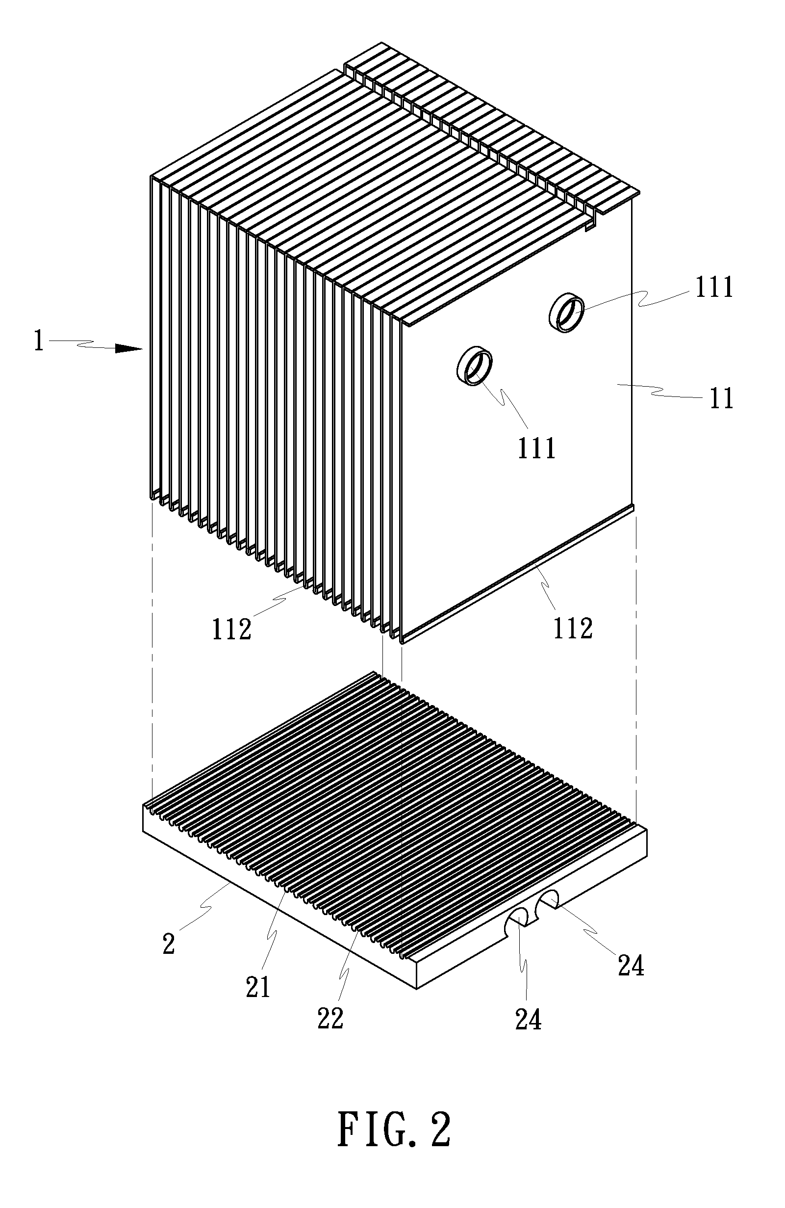
[0022]The radiation fin module 1 is a heat-dissipation block member formed of a stack of radiation fins 11. Each radiation fin 11 has at least one, for example, two mounting through holes 111 for receiving the heat pipes 3 in a tight fit manner, and a bottom end edge crimped into a root portion 112.

[0023]The base panel 2 is a metal panel extruded from aluminum, copper or other thermal conductive material, having a plurality of mounting grooves 21 arranged in parallel on the top wall thereof for receiving the root portions 112 of the radiation fins 11 of the radiation fin module 1, a plurality of elongated V-grooves 22 respectively arranged in parallel on the top wall between each two adjacent mounting grooves 21, and at least one, for example, two locating grooves 24 formed on the...


PUM


Abstract

A cooler device includes a base panel, which has multiple mounting grooves on the top wall and multiple locating grooves on the bottom wall, a radiation fin module formed by stacking up multiple radiation fins, each radiation fin having multiple mounting through holes and a root portion that is respectively riveted to the mounting grooves of the base panel, and multiple U-shaped heat pipes, each heat pipe having a first extension arm respectively and tightly fitted into the mounting through holes of the radiation fins and a second extension arm respectively and tightly fitted into the locating groove of the base panel and kept in flush with the bottom wall of the base panel for direct contact with a CPU or the like to transfer heat energy from the CPU or the like to the radiation fins for quick dissipation.

Description

BACKGROUND OF THE INVENTION[0001](a) Field of the Invention[0002]The present invention relates to a cooler device for cooling a semiconductor electronic device or the like. More particularly, it relates to such a cooler device which has heat pipes directly press-fitted into respective locating grooves on the bottom wall of a base panel and kept in flush with the bottom wall for direct contact with a CPU or the like to transfer heat energy from the CPU to a radiation fin module for quick dissipation.[0003](b) Description of the Prior Art[0004]A conventional heat pipe-attached cooler device generally comprises a radiation fin module, a base panel, and one or more heat pipes. The radiation fin module is formed of a stack of radiation fins and directly bonded to the top wall of the base panel with solder paste. The heat pipes are bonded to the radiation fin module and the base panel with solder paste. If the base panel and the heat pipes are made of different aluminum materials, a nicke...

Claims


Application Information

Patent Timeline
Patent Type & Authority Applications(United States)
IPC IPC(8): F28F7/00
CPCG06F1/20G06F2200/201H01L21/4882H01L23/3672H01L23/427H01L2924/0002F28D15/0275H01L2924/00
Inventor HUANG, TSUNG-HSIEN
Owner HUANG TSUNG HSIEN
Why Eureka
Try Eureka