Apparatus, assembly and process for injecting fluid into a subterranean well

Active Publication Date: 2009-08-06
PCS FERGUSON
View PDF53 Cites 43 Cited by
  • Summary
  • Abstract
  • Description
  • Claims
  • Application Information

AI Technical Summary

Benefits of technology

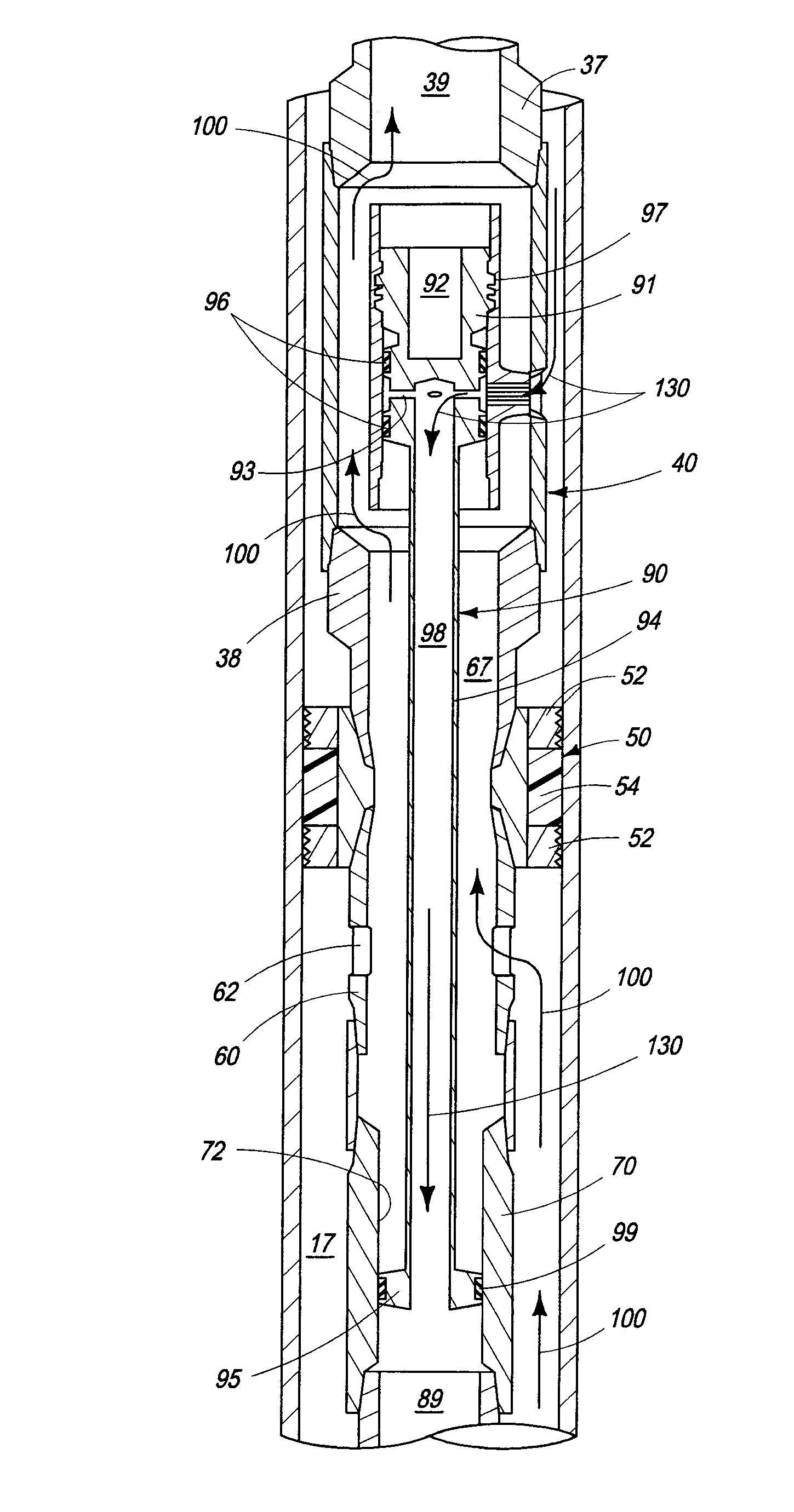
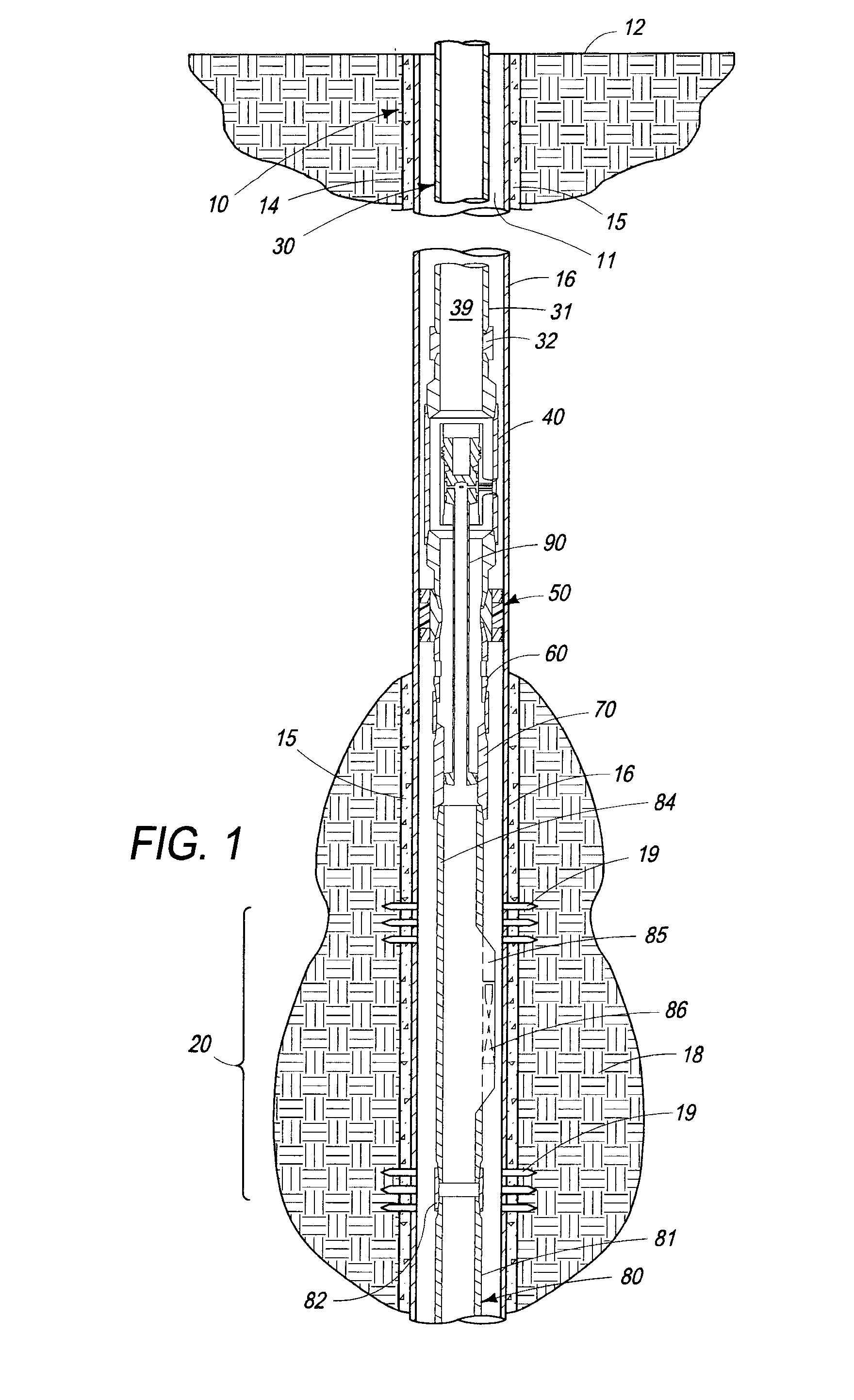
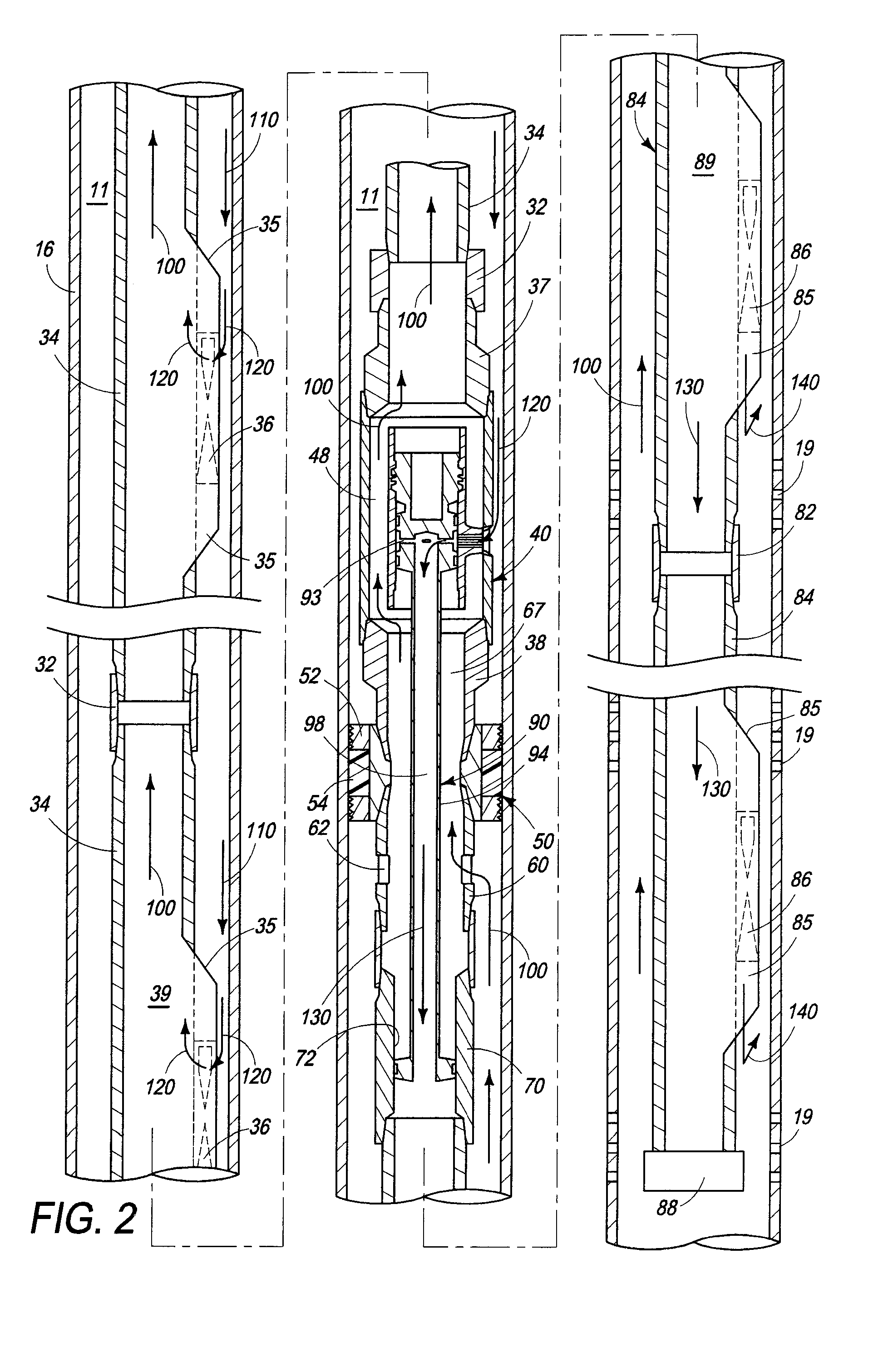
[0010]In another characterization of the present invention, an assembly is provided which has first and second sections of tubing string and a segregation member. A first section of a tubing string extends from the surface of the earth into a subterranean well bore and has a packer secured to the lower end thereof. The first section has a generally axial bore therethrough and one or more openings through the wall thereof. A second section of the tubing string is secured to the packer and extends into the subterranean well bore below the packer. The second section has a generally axial bore therethrough and one or more openings through the wall thereof. A segregation member is releasably secured to the first section and extends through the packer and into the second section of the tubing string. A segregation member has a bore extending through a portion thereof which is in fluid communication with the one or openings through the wall of the first section so as to define a flow path from the surface of the earth through a first annulus defined between the first section and the well bore, the one or more openings, and the bore in the segregation member.
[0011]In yet another characterization of the present invention, a subterranean well is provided comprising a tubing string positioned within a casing in a subterranean well and having a packer secured intermediate the length thereof and sealingly engaging the casing. At least one piece of equipment is secured to the tubing string below the packer and is capable of being retrieved on wireline that is conveyed within the tubing string.
[0012]In a further characterization of the present invention, a process is provided for equipping a subterranean well for a gas lift operation. A tubing string having a packer secured intermediate the length thereof is positioned into a subterranean well. The packer sealingly enga

Problems solved by technology

However, the pressure in many wells is or becomes insufficient to permit the well to be produced by conventional gas lift techniques an

Method used


Image

  • Apparatus, assembly and process for injecting fluid into a subterranean well
  • Apparatus, assembly and process for injecting fluid into a subterranean well
  • Apparatus, assembly and process for injecting fluid into a subterranean well

Examples


example

[0030]A workover rig is moved onto a well, blow out prevention equipment is installed and the existing 2.875 inch outside diameter (“OD”) production tubing is removed from the 5.5 inch OD production casing in the well. The well is cleaned of any debris by running a tubing bailer on the 2.875 inch tubing to the total depth of the well of 9,000 feet. The tubing and bailer are removed from the well. The integrity of the casing above the top of the perforations in the well is determined by running a 5.5 inch OD packer on the 2.875 inch tubing to a depth of 7,500 feet. The packer is mechanically set and the annulus between the 2.875 inch tubing and the 5.5 inch casing above the packer is filled with completion fluid. The blow out prevention equipment is closed at the surface and the fluid in the annulus is pressurized to 1500 pounds per square inch to determine casing integrity. Once casing integrity has been established, the packer is released and the tubing and the packer are removed f...


PUM


Abstract

Apparatus, assembly and process for allowing gas lift operations to be conducted along a relatively long perforated interval below a packer in a subterranean well. An elongated segregation member is lowered into locking engagement with a bypass mandrel secured to a tubing string above the packer. This segregation member is configured and dimensioned to define two fluid flow paths. A first flow path extends from the surface of the earth through the annulus formed between the tubing string above the packer and casing secured in the well, the bypass mandrel, a bore through a portion of the segregation member and the interior of the tubing string below the packer. A second flow path extends from the subterranean region penetrated by the well through the annulus formed between the tubing string below the packer and casing secured in the well, the annulus between the segregation member and the packer, and the interior of the tubing string above the packer. Fluid produced into the well from the subterranean region is conveyed to the surface via the second flow path and can be assisted by gas injected into the first flow path via retrievable gas lift valves in the tubing string above and below the packer. Pressurized gas is conveyed via the first flow path to these retrievable gas lift valves.

Description

BACKGROUND OF THE INVENTION[0001]1. Field of the Invention[0002]The present invention relates to an apparatus, assembly and process for permitting fluid to be conveyed into a subterranean well via retrievable equipment positioned in tubing below a packer, and more particularly, to such apparatus, assembly and process for permitting gas lift to be conducted in a subterranean well below a packer wherein wireline retrievable gas lift valves are employed below the packer.[0003]2. Description of related Art[0004]To produce fluids, such as hydrocarbons, from a subterranean formation, a well is drilled from the surface to a depth sufficient to capture the fluids of interest. The well is typically completed by cementing a string of tubulars, i.e. a casing string, in the well and establishing fluid communication between the well and the formation(s) and / or zone(s) of interest by forming perforations through the casing and into the formation(s) and / or zone(s) of interest. Such perforations ca...

Claims


Application Information

Patent Timeline
IPC IPC(8): E21B43/18
CPCE21B43/122E21B17/18E21B33/12E21B43/123
Inventor STEPHENSON, PEARL E.HOLMES, WILLIAM D.
Owner PCS FERGUSON
Why Eureka
Try Eureka