Energy absorbers, connectors and horizontal lifeline systems

a technology of connectors and energy absorbers, applied in the direction of shock absorbers, elastic dampers, scaffold accessories, etc., can solve the problems of large total length/area of spent straps, large force requirements, and large size of spent straps. achieve the effect of reducing strength

Active Publication Date: 2009-08-06
HONEYWELL INT INC
View PDF18 Cites 43 Cited by
  • Summary
  • Abstract
  • Description
  • Claims
  • Application Information

AI Technical Summary

Benefits of technology

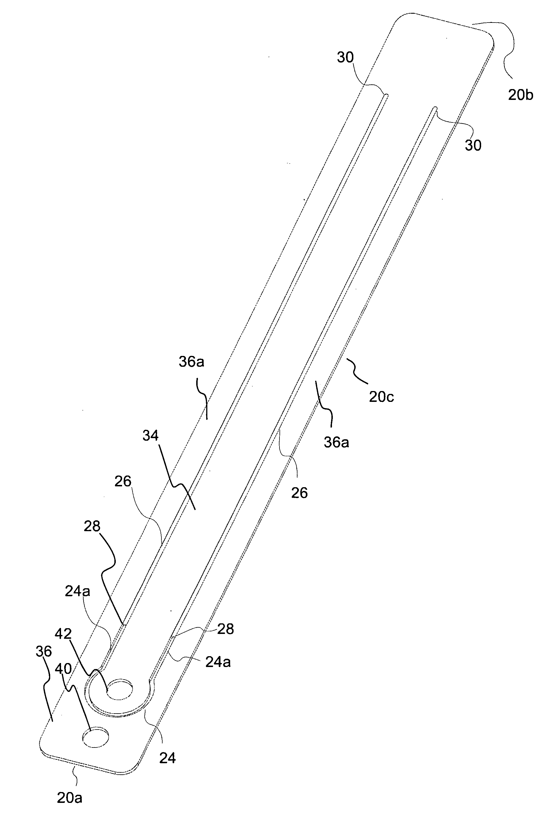
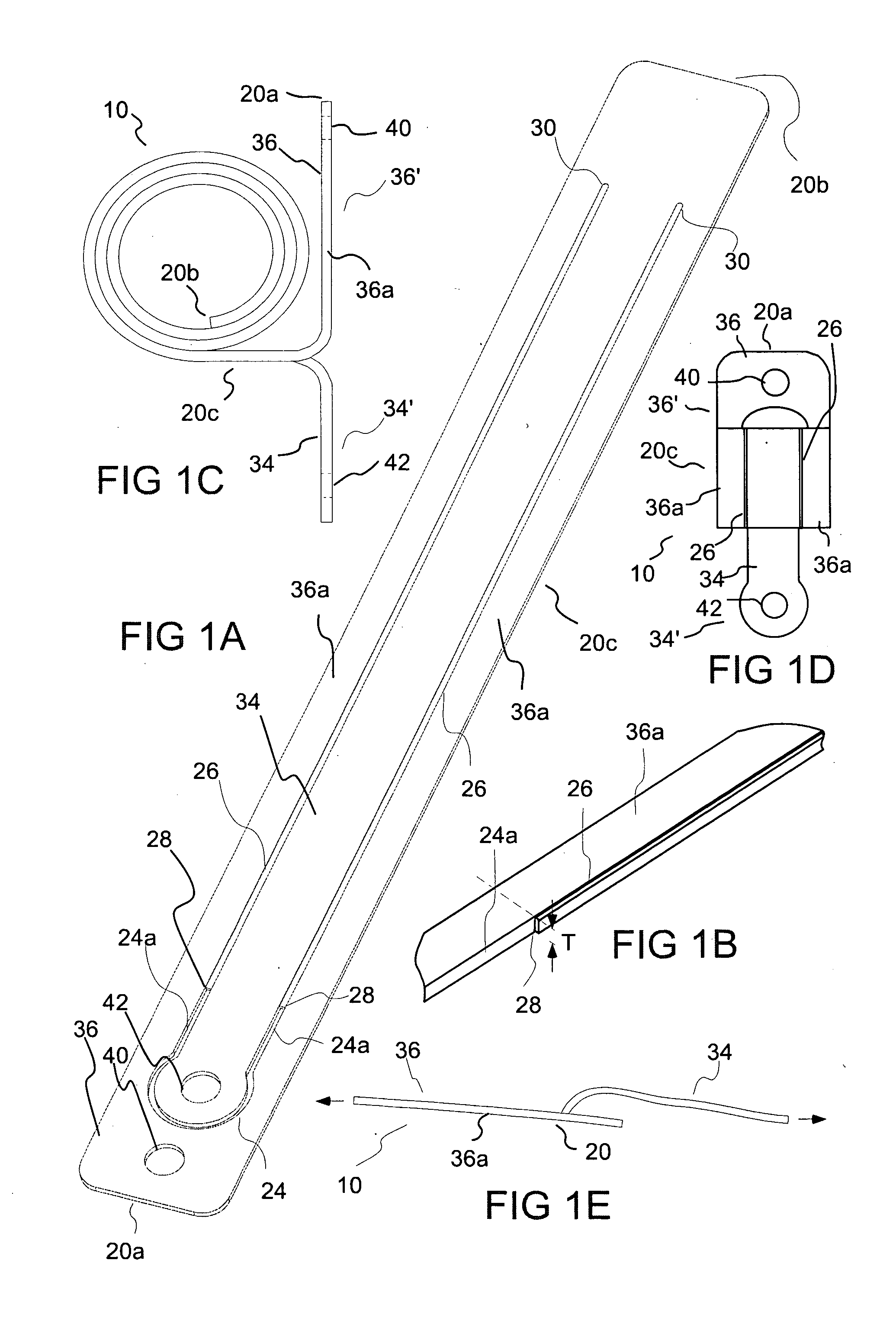
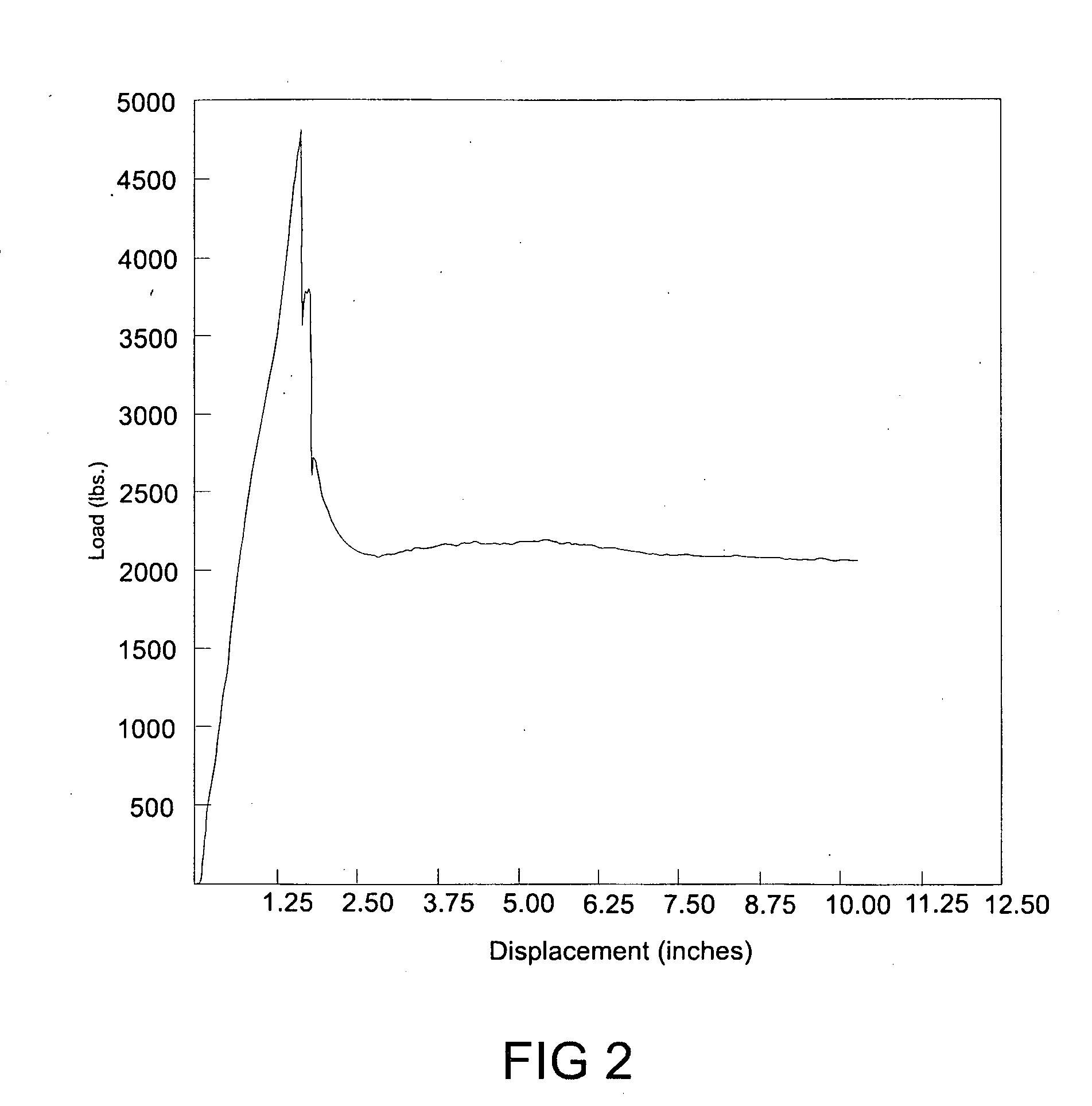
[0010]In a number of embodiments, the present invention provides energy absorbers or energy absorber systems that include one or more transition regions in which tearing or other deformation to absorb energy is dynamically initiated during use. The transition region of the present invention has a defined design that results in a predictable change in load over the length of the transition region. In the case of an energy absorber for a horizontal lifeline system, for example, spikes in load above a predetermined value (for example, 2500 lbs. as described above) are preferably avoided during the dynamic initiation of energy absorption and a generally constant load at or below the predetermined value is maintained thereafter. The generally constant load is preferably as close to the predetermined value as possible. In several embodiments of the present invention, a gradual increase in load occurs over the transition region until a path of reduced strength is reached over which the load is generally constant.
[0036]In another aspect, the present invention provides a stanchion or stanchion system for use in connection with a lifeline including a stanchion post and a connector moveably connected to the stanchion post. The connector includes a first connector element (for example, a passage) to connect to the lifeline and a second connector element (for example, a second passage) to connect to an anchor. The connector can also, for example, include at least a first extending slot. The stanchion can further include a first attachment member that passes through the first slot to connect the connector to the stanchion post so that the connector can slide relative to the first attachment member along the length of the first slot.

Problems solved by technology

Nonetheless, in certain systems, horizontal lifeline stanchions can be subjected to substantial force.
Although there are many types of energy absorbers that perform this function, a design problem common to all such energy absorbers is how to accommodate the force requirements at initial deployment or activation.
Several other problems are associated with energy absorbers including a strip or strap of material that is tom.
Although the strap can, for example, be coiled by the manufacturer so that the energy absorber originally takes up little space, the activation and full (or even partial) deployment (including both uncoiling and tearing) of the energy absorber results in a spent strap that is relatively large in total length / area.
Such an energy absorber may not be suitable for uses in which there is limited space for the spent energy absorber or in which it is desirable to limit total displacement.

Method used


Image

  • Energy absorbers, connectors and horizontal lifeline systems
  • Energy absorbers, connectors and horizontal lifeline systems
  • Energy absorbers, connectors and horizontal lifeline systems

Examples


Embodiment Construction

[0095]Several embodiments of the present invention are discussed herein in connection with use of energy absorbers of the present invention in a fall protection systems such as a horizontal lifeline systems. However, one skilled in the art appreciates that the energy absorbers of the present invention can be used in a wide variety of systems in which energy absorption in required to, for example, protect against damage to equipment and / or to protect against injury to individuals.

[0096]As used herein and in the appended claims, the singular forms “a,”“an”, and “the” include plural references unless the content clearly dictates otherwise. Thus, for example, (unless clearly indicated otherwise) reference to “a path” includes a plurality of paths and equivalents thereof known to those skilled in the art, and so forth, and reference to “the path”, is a reference to one or more such paths and equivalents thereof known to those skilled in the art, and so forth.

[0097]Terms such as “left”, “...


PUM


Abstract

An energy absorber including a strap including at least a first path of relatively reduced strength extending over at least a portion of the length of the strap. The energy absorber also includes at least a first transition region including a first initial point where tearing begins along the first transition region when a force above a threshold force is applied (to the energy absorber / strap) and a first end point. The first end point is in operative connection with a first point on the first path so that tearing continues along the first path after tearing along the first transition region. A gradual increase in load occurring as tearing occurs along the transition region.

Description

CROSS-REFERENCE TO RELATED APPLICATION[0001]This application claims benefit of U.S. Provisional Patent Application Ser. No. 61 / 026,530, filed Feb. 6, 2008 and U.S. Provisional Patent Application Ser. No. 61 / 026,653, filed Feb. 6, 2008, the disclosures of which are incorporated herein by reference.BACKGROUND OF THE INVENTION[0002]The present invention relates to energy absorbers or shock absorbers and energy transferring connectors and, particularly to energy absorbers and connectors for use in connection with safety systems such as horizontal lifeline systems.[0003]The following information is provided to assist the reader to understand the invention disclosed below and the environment in which it will typically be used. The terms used herein are not intended to be limited to any particular narrow interpretation unless clearly stated otherwise in this document. References set forth herein may facilitate understanding of the present invention or the background of the present inventio...

Claims


Application Information

Patent Timeline
Patent Type & Authority Applications(United States)
IPC IPC(8): A62B35/04F16F7/12
CPCA62B35/04E04G21/3233F16F7/128F16F7/123E04G21/3261E04G5/045E04G21/3242E04G21/3276E04G21/329E04G21/3295
Inventor PARKER, THOMAS W.WINSLOW, DAVID A.MANSON, ERIC M.ANDERSON, PRESTON L.
Owner HONEYWELL INT INC
Why Eureka
Try Eureka