
Mold for injection molding and an injection molding device/method with surface quality improvement ability

a technology of injection molding and molds, which is applied in the field of molds for injection molding and injection molding devices/methods with surface quality improvement ability, can solve the problems of poor injection molding, inability to maintain the temperature of injected plastic, and rapid drop of the mold surface temperature, so as to improve the surface quality of the resulting products, improve the amount of surface defects, and improve the effect of surface quality

Inactive Publication Date: 2009-08-06
CHUNG YUAN CHRISTIAN UNIVERSITY
View PDF8 Cites 8 Cited by
  • Summary
  • Abstract
  • Description
  • Claims
  • Application Information

AI Technical Summary

Benefits of technology

[0005]In view of the disadvantages of prior art, one object of the present invention is to provide an injection molding device / method with surface quality improvement ability, by which the amount of surface defects in its resulting injection molding products can be reduced and thus the surface quality of the resulting products is improved.
[0006]To achieve the above object, the present invention provides an injection molding device and method capable of using a process of feeding a film into its mold cavity for achieving good surface heat resistance effect.
[0010]With the aforesaid device and method, the surface temperature dissipating rate of the plastic filled in the mold can be reduced so that the mobility of the melt plastic filled inside the mold can be enhanced while enabling the weld line appeared in a heating area of the resulting injection molding product to fade away.

Problems solved by technology

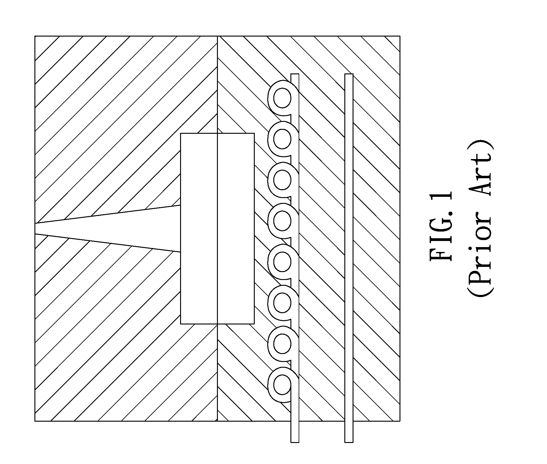
However, as the mold used in conventional injection molding are usually made of steel that has good heat conductivity, no matter it is preheated by electric heating, high cycle wave, or infrared means, the surface temperature of the mold is going to drop rapidly during the period between the closure of mold and the injection of plastic into its mold cavity.
Consequently, the temperature of the injected plastic can not be maintained which is the cause of poor injection molding.
That is, if the mold for injection molding is made of a material with good heat conductivity, the melt plastic in the mold cavity will be affected by the mold and thus it is cooled before it is molded so that defects such as premature failures, overly briquetting pressure, and rough surface could be caused.

Method used


Image

  • Mold for injection molding and an injection molding device/method with surface quality improvement ability
  • Mold for injection molding and an injection molding device/method with surface quality improvement ability
  • Mold for injection molding and an injection molding device/method with surface quality improvement ability

Examples


Embodiment Construction

[0020]For your esteemed members of reviewing committee to further understand and recognize the fulfilled functions and structural characteristics of the invention, several exemplary embodiments cooperating with detailed description are presented as the follows.

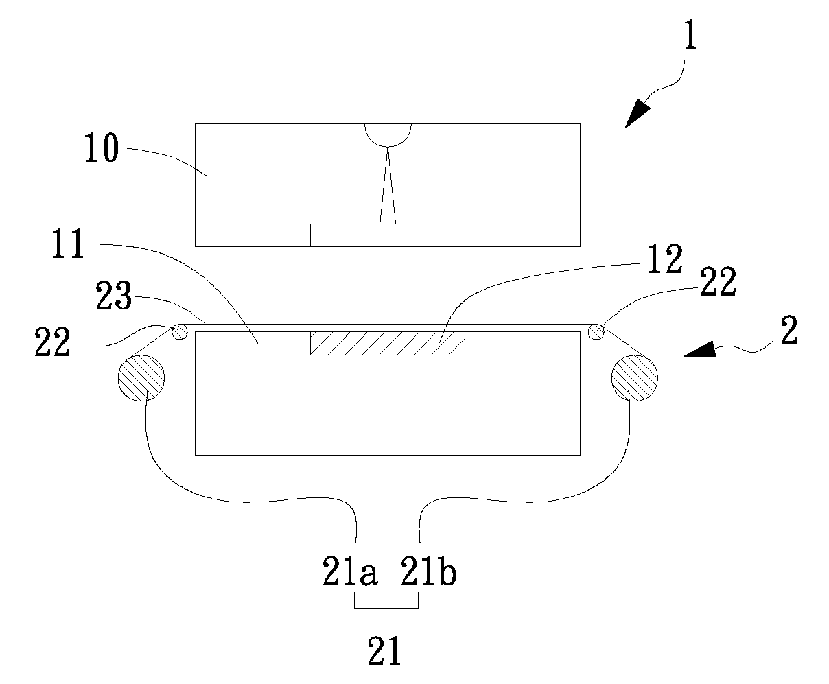
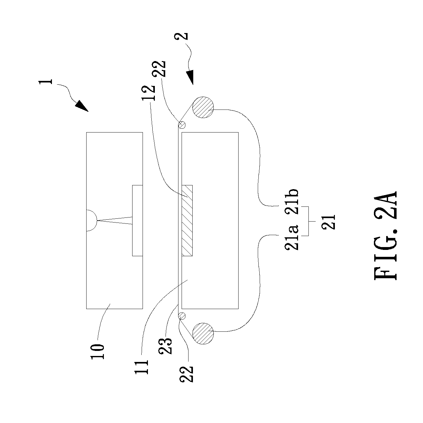
[0021]Please refer to FIG. 2A to FIG. 2C, which are schematic diagrams showing consecutive steps of an operating injection molding device according to a first embodiment of the invention. In FIG. 2A, the injection molding device with surface quality improvement ability comprises a mold 1 and a film feeder 2; in which the mold 1 is composed of a first mold piece 10 and a second mold piece 11 having a suction unit 12 configured thereat; and the film feeder 2 is used for providing a film to be attracted by the suction unit 12. It is noted that the suction unit 12 is able to attract the film for enabling the attracted film to adhere flatly on a surface of the mold 1, and the suction unit 12 can be a pneumatic type suction device o...


PUM

PropertyMeasurementUnit
surface temperature dissipating rateaaaaaaaaaa
surface qualityaaaaaaaaaa
diameteraaaaaaaaaa

Abstract

A mold for injection molding and an injection molding device / method with surface quality improvement ability are disclosed, in which the injection molding device comprises: a mold including a first mold piece and a second mold piece; and a film feeder. In an exemplary embodiment, the second mold piece is configured with a suction unit in a manner that the film feeder is enabled to provide a film to the suction unit.

Description

FIELD OF THE INVENTION[0001]The present invention relates to a mold for injection molding and an injection molding device / method with surface quality improvement ability, and more particularly, to an injection molding device and method capable of feeding a film into the mold cavity thereby achieving good surface heat resistance effect.BACKGROUND OF THE INVENTION[0002]Generally, in order to enable a melt plastic to flow steadily after it is fed into a mold for injection molding, it is important to keep the temperature of the melt plastic from dropping too fast so that the mobility of the melt plastic can be maintained for preventing the cause of deflect in the resulting products of the injection molding. Therefore, it is commonly seen in those conventional injection molding devices of using a heater to preheat it mold cavity to a specific temperature before injection molding for achieving a purpose of preventing the melt plastic / s temperature from dropping too fast after it is being ...

Claims


Application Information

Patent Timeline
Patent Type & Authority Applications(United States)
IPC IPC(8): B29C45/14B29C45/03
CPCB29C33/58B29C33/68B29C45/0046B29C2045/1477B29C45/14754B29C45/37B29C2033/023B29C45/14016
Inventor CHEN, SHIA-CHUNGCHANG, JEN-ANWANG, HO-HSIANGHSU, PING-SHUN
Owner CHUNG YUAN CHRISTIAN UNIVERSITY
Learn More