Pressure Balanced Shaft Seal Assembly

a technology of pressure balanced shaft and seal assembly, which is applied in the direction of engine seals, shafts and bearings, rolling contact bearings, etc., can solve the problems of reducing or lowering the efficiency and efficacy of sealing members, failure to provide an adequate seal, and maximizing the potential for shaft to bore misalignmen

Inactive Publication Date: 2009-08-06
INPRO INC
View PDF3 Cites 17 Cited by
  • Summary
  • Abstract
  • Description
  • Claims
  • Application Information

AI Technical Summary

Benefits of technology

[0010]The present art offers improved shaft sealing and product seal performance over the prior art. The shaft seal assembly solution disclosed and claimed herein allows both tight or low running clearance between

Problems solved by technology

Typically the solutions presented have failed to provide an adequate seal while allowing for an acceptable amount of shaft misalignment during operation.
The problem is especially acute in product seals where the potential for shaft to bore misalignment may be maximized.
“Loose” running for adjustment or response to operational conditions, especially misalignment of the shaft with respect to the stator or stationary member, however, typically reduces or lowers the efficiency and efficacy of sealing members.
Shaft misalignment is also a problem with “contact” seals because the contact between the seal and misaligned shaft typically results in greater wear.
Abrasiveness of the product also affects the wear pattern and the useful life of the contact seals.
Prior attempts to use fluid pressure (either vapor or liquid) to seal both liquid and solid materials in combination with sealing members such as labyrinth seals or contact seals have not been entirely satisfactory because of the “tight” or low clearance necessary to create the required pressure differential between the seal and the product on the

Method used


Image

  • Pressure Balanced Shaft Seal Assembly
  • Pressure Balanced Shaft Seal Assembly
  • Pressure Balanced Shaft Seal Assembly

Examples


first embodiment

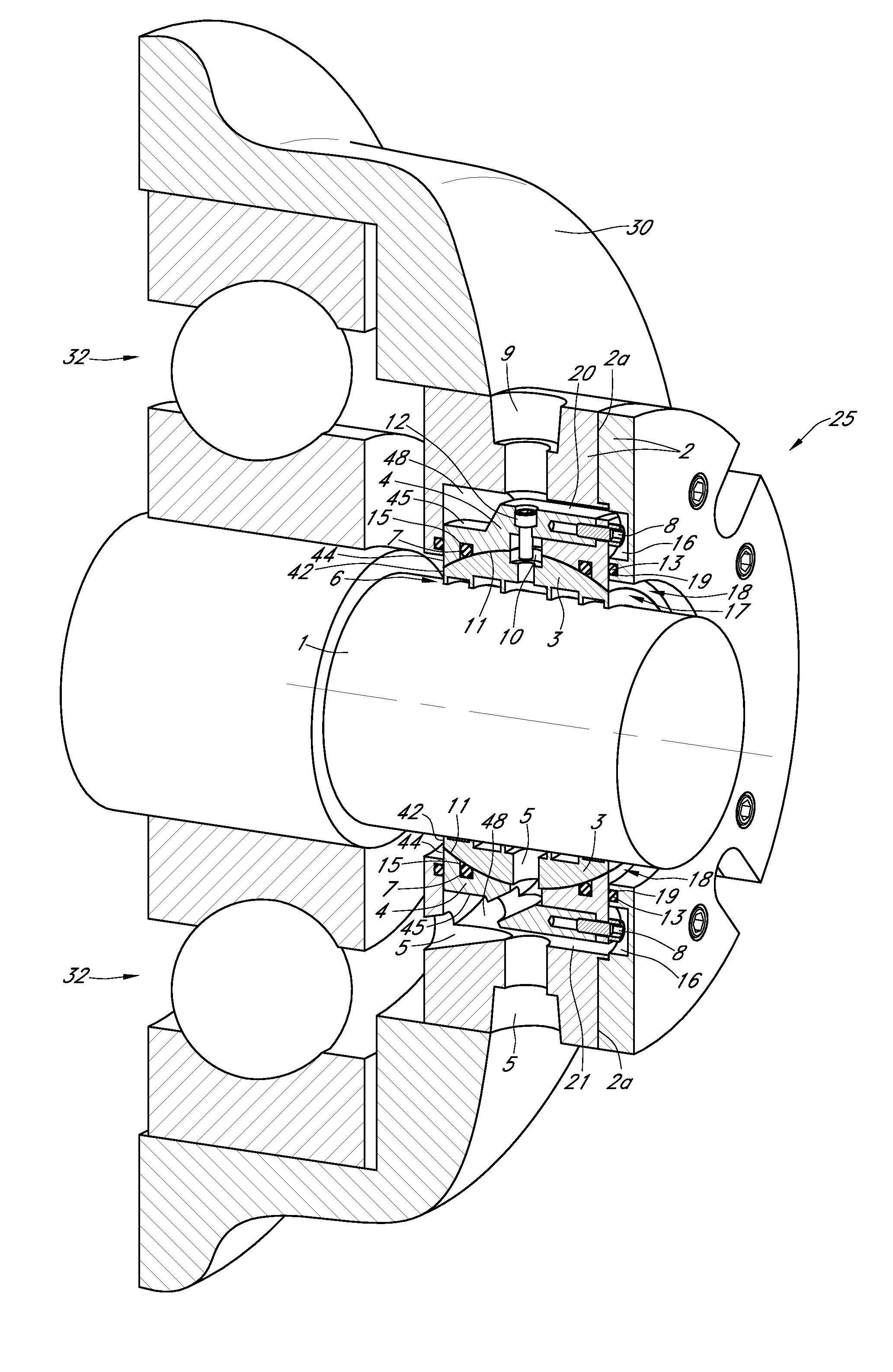
[0039]FIGS. 1-5 provide a view of the shaft seal assembly 25 that allows for sealing various lubricating solutions within bearing housing 30. FIGS. 6 and 7 provide alternative embodiments of the shaft seal assembly 25 wherein sealing fluids are used. Applicant herein defines sealing fluids to include both liquids and vapors. Applicant considers air, nitrogen, water and steam as well as any other fluid which may work with the proposed shaft seal assembly to provide a pressurized fluid barrier for any and all embodiments disclosed herein to be within the purview of the present disclosure. The gas or fluid chosen is based on process suitability with the product to be sealed.

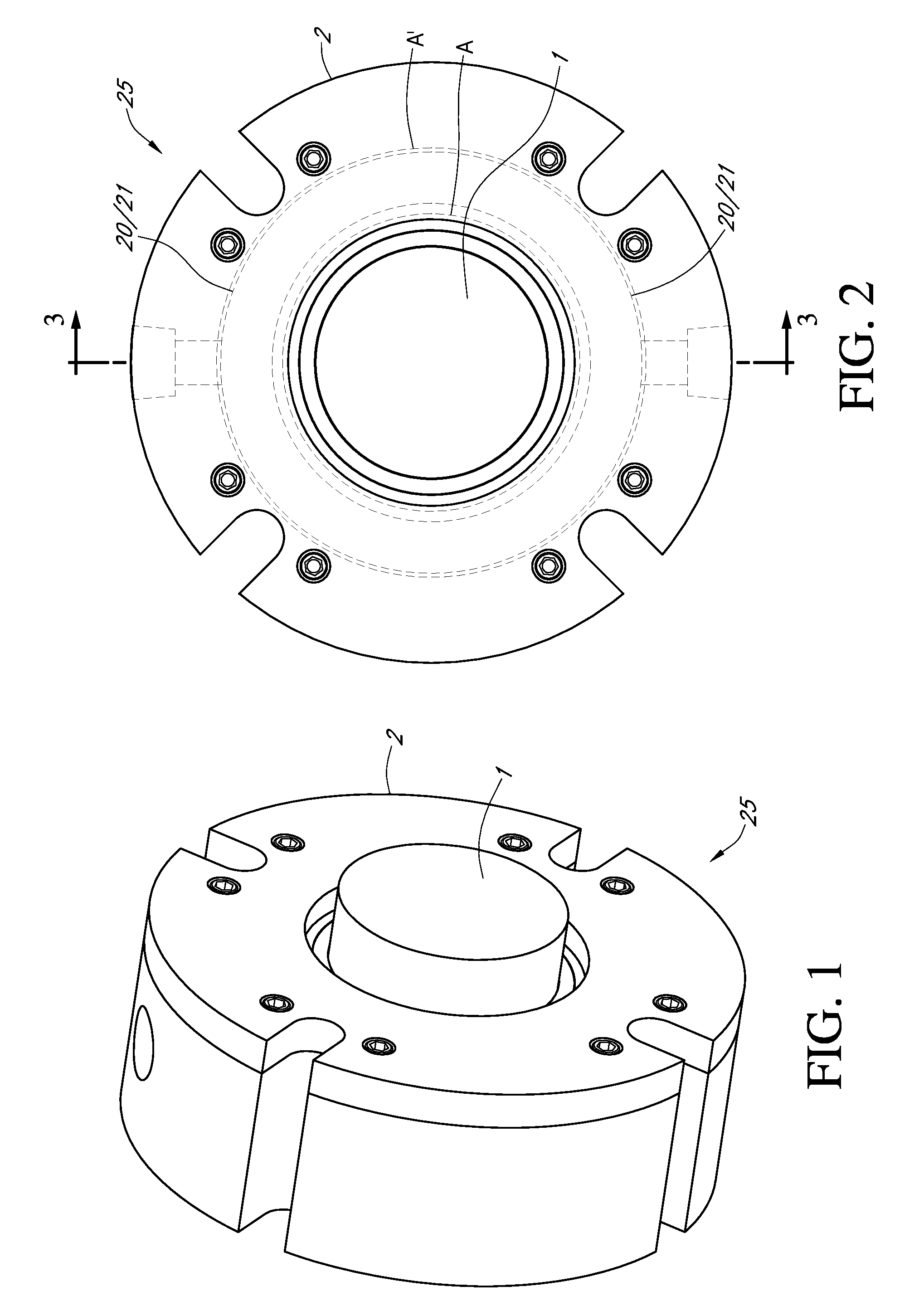
[0040]FIG. 1 is a perspective exterior view of the shaft seal assembly 25 arranged and engaged with a shaft 1 inserted through the fixed stator 2 of shaft seal assembly 25. FIG. 2 is an exterior end view of the shaft seal assembly with shaft 1 aligned within the shaft seal assembly 25.

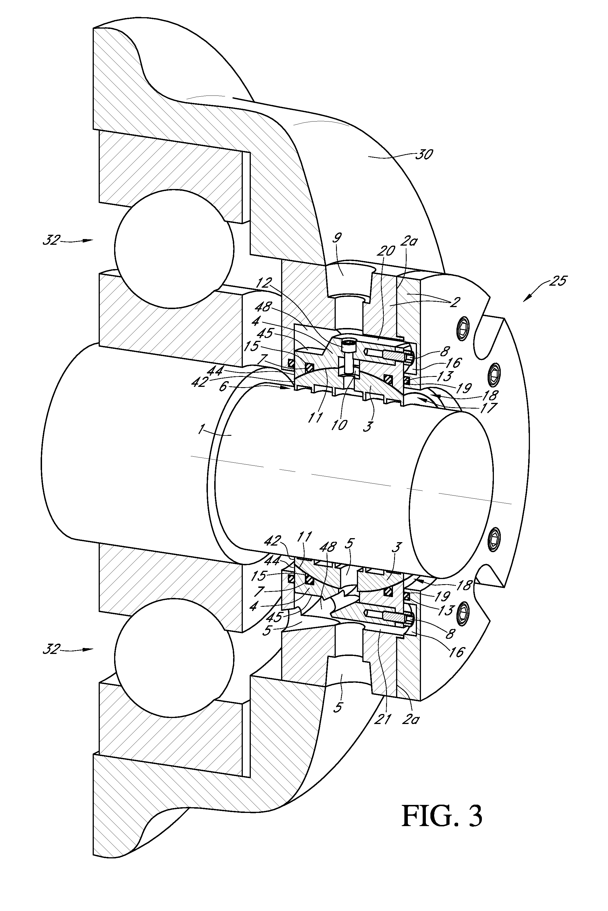
[0041]FIG. 3 is a sectional vie...

second embodiment

[0055]FIG. 6 is a sectional view of the shaft seal assembly 25 as shown in FIG. 2 for over-pressurization with alternative labyrinth seal pattern grooves 14. In this figure the labyrinth seal pattern grooves 14 are composed of a friction reducing substance such as polytetrafluoroethylene (PTFE) that forms a close clearance to the shaft 1. PTFE is also sometimes referred to as Teflon® which is manufactured and marketed by Dupont. PTFE is a plastic with high chemical resistance, low and high temperature capability, resistance to weathering, low friction, electrical and thermal insulation, and “slipperiness.” The “slipperiness” of the material may also be defined as lubricous or adding a lubricous type quality to the material. Carbon or other materials may be substituted for PTFE to provide the necessary sealing qualities and lubricous qualities for labyrinth seal pattern grooves 14.

[0056]Pressurized sealing fluids are supplied to over-pressurize the lubricious labyrinth pattern 26 as ...


PUM


Abstract

A pressure balanced shaft seal assembly that allows a seal to dynamically respond to angular or radial misalignment of a shaft is disclosed. The pressure balanced shaft seal assembly includes a fixed stator, a floating stator, and a labyrinth seal. In one embodiment, the floating stator and labyrinth seal are mounted within an annular groove formed in the fixed stator such that the floating stator and labyrinth seal may move a predetermined amount in the radial direction with respect to the fixed stator. A spherical interface between the labyrinth seal and floating stator may allow the labyrinth seal to pivot with respect to the floating stator during angular misalignment of a shaft around which the pressure balanced shaft seal assembly is mounted. A pressure balancing annular channel formed in the floating stator allows pressurized seal fluid to balance the axial pressure exerted on the floating stator by the process fluid.

Description

[0001]Applicant states that this utility patent application claims priority from U.S. patent application Ser. No. 12 / 156,476 and is a continuation-in-part of said utility patent application, which claimed priority from U.S. patent application Ser. No. 11 / 405,207 (now U.S. Pat. No. 7,396,017) as a continuation of said utility patent application, which claimed priority from both U.S. patent application Ser. No. 10 / 177,067 (now U.S. Pat. No. 7,090,403), as a continuation in-part, and Provisional Pat. App. No. 60,697,434, all of which are incorporated by reference herein.FIELD OF THE INVENTION[0002]The present invention relates to a pressure balanced shaft seal assembly with multiple embodiments. A labyrinth seal for retaining lubrication solution within the bearing cavity of a hub assembly, such as a bearing housing, for application to a rotatable shaft to keep contaminants out of the bearing cavity while allowing a sealing fluid to balance the pressure on the process sides of the seal...

Claims


Application Information

Patent Timeline
IPC IPC(8): F16J15/447F16J15/46
CPCF16J15/187F16J15/40F16J15/54F16J15/4472F16J15/441
Inventor ORLOWSKI, DAVID C.HOELHE, NEIL F.
Owner INPRO INC
Why Eureka
Try Eureka