Rear vehicle body structure

a rear vehicle and body technology, applied in the direction of roofs, vehicle arrangements, transportation and packaging, etc., can solve the problems of lowering the dynamic performance of the vehicle, increasing manufacturing costs, and affecting fuel economy

Active Publication Date: 2009-08-06
HONDA MOTOR CO LTD
View PDF2 Cites 45 Cited by
  • Summary
  • Abstract
  • Description
  • Claims
  • Application Information

AI Technical Summary

Benefits of technology

[0011]In view of such problems of the prior art, a primary object of the present invention is to provide a

Problems solved by technology

As the current vehicle body typically has a monocoque structure combining a number of sheet steel pieces having relatively small thicknesses, it is a challenge to achieve a required mechanical strength and rigidity against a rear end crash while forming a space for receiving a spare tire.
The rigidity and mechanical strength of a vehicle body can be increased by increasing the thickness of the sheet steel, but it has the disadvantage of increasing the manufacturing cost, impairing the fuel economy and lowering the dynamic performance of the vehicle.
If the rear vehicle body structure is configured to drop the rear end of a spare tire at the time of a rear end collision as proposed in Japanese patent No. 3620288, the deformation of the spare tire pan cannot be effectively utilized for the absorption of the impact energy of a rear end collision, and this limits the capability of the rear vehicle body to effectively absorb the impact energy at the time of a rear end collision particularly when hit by a tall vehicle having a front bumper at a relatively high position.
However, because the front vertical wall of the spare tire pan hangs over the front part of the spare tire, the spare tire is caught by this overhang as the rear end thereof is raised due to the impact of a

Method used


Image

  • Rear vehicle body structure
  • Rear vehicle body structure
  • Rear vehicle body structure

Examples


Embodiment Construction

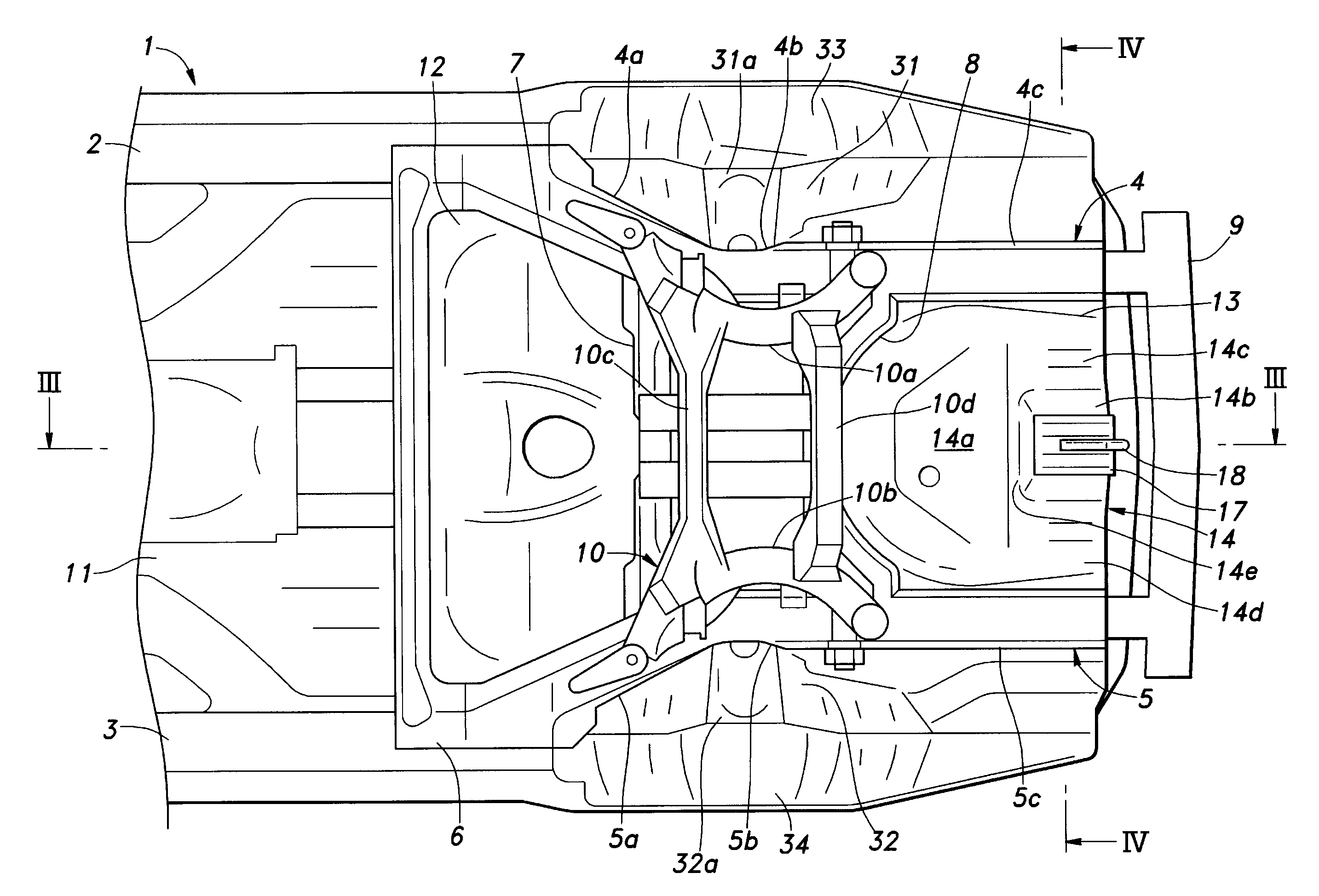
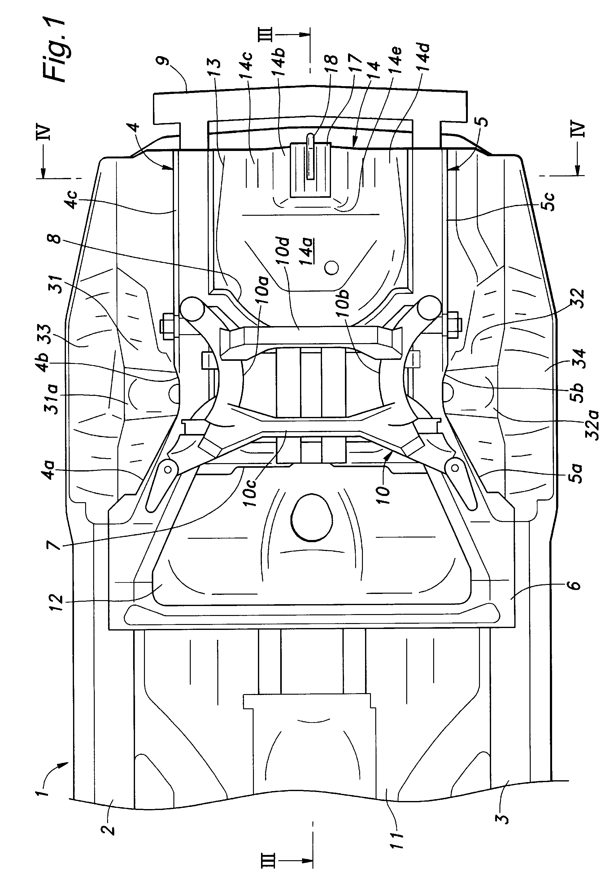
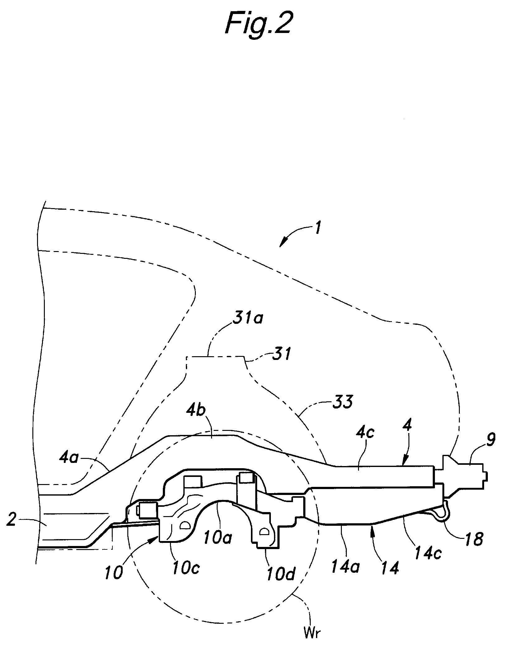
[0025]FIG. 1 is a bottom view of a rear vehicle body structure embodying the present invention, FIG. 2 is a simplified side view of the vehicle body shown in FIG. 1, and FIG. 3 is a sectional view taken along line III-III of FIG. 1. This vehicle body 1 comprises, for a floor frame structure thereof, a pair of side sills 2 and 3 extending along either side of the vehicle body, a pair of rear side frames 4 and 5 extending from the rear ends of the corresponding side sills 2 and 3, a middle floor cross member 6 extending laterally across the width of the vehicle body and connecting the rear ends of the side sills 2 and 3 to each other, a rear floor cross member 7 connecting middle portions 4b and 5b of the rear side frames 4 and 5 to each other, and a spare tire pan cross member 8 connecting rear portions 4c and 5c of the rear side frames 4 and 5 to each other.

[0026]The front end of each rear side frame 4, 5 is attached to an inboard side of the corresponding side sill 2, 3 with a cert...


PUM


Abstract

In a rear vehicle body structure, a spare tire is received in a spare tire pan in a rear end up slanted orientation, the front end of the spare tire is prevented from forward movement by a spare tire pan cross member, and a rear bottom of the spare tire pan is reinforced. At the time of a rear end crash, the spare tire is tilted substantially to an upright orientation around the front end, and the spare tire pan is deformed such that the rear bottom is folded upon a front bottom wall in the shape of letter Z as seen from side so that the spare tire pan provides a long deformation stroke, and is utilized for absorbing the impact energy of the rear end crash. Preferably, the rear bottom comprises an elevated horizontal part and a stepped portion defining a front edge of the elevated horizontal part.

Description

TECHNICAL FIELD[0001]The present invention relates to a rear vehicle body structure, and in particular to a rear vehicle body structure that includes a spare tire pan for receiving a spare tire therein.BACKGROUND OF THE INVENTION[0002]A passenger vehicle is typically provided with a spare tire pan in a rear part of the vehicle body. As the current vehicle body typically has a monocoque structure combining a number of sheet steel pieces having relatively small thicknesses, it is a challenge to achieve a required mechanical strength and rigidity against a rear end crash while forming a space for receiving a spare tire.[0003]The rigidity and mechanical strength of a vehicle body can be increased by increasing the thickness of the sheet steel, but it has the disadvantage of increasing the manufacturing cost, impairing the fuel economy and lowering the dynamic performance of the vehicle. Therefore, there have been various proposals to increase the mechanical strength of a rear part of a ...

Claims


Application Information

Patent Timeline
IPC IPC(8): B62D25/08
CPCB62D21/152B62D25/2027B62D25/087
Inventor YAMAGUCHI, TOSHIZUMINUSHII, HIROTSUYUZAKI, TAKUMI
Owner HONDA MOTOR CO LTD
Why Eureka
Try Eureka