Brake system and method

a technology of brake system and brake, applied in the direction of brake system, brake components, transportation and packaging, etc., can solve the problems of shortening the life of the brake, affecting the operation of the brake,

Active Publication Date: 2009-08-06
MERITOR HEAVY VEHICLE BRAKING SYST (UK) LTD
View PDF16 Cites 64 Cited by
  • Summary
  • Abstract
  • Description
  • Claims
  • Application Information

AI Technical Summary

Benefits of technology

[0010]A third aspect of the present invention provides a system for adjusting a brake force to be applied by a brake including a module for estimating a weight of a vehicle to which the brake is fitted, a module for determining an angle of incline upon which the vehicle is positioned, and a control unit for calculating a sufficient brake force to be applied according to predetermined criteria based upon the estimated weight and the determined angle of incline to maintain the vehicle in a stationary state. The control unit is configured to signal the brake to apply the calculated amount of force.

Problems solved by technology

It has now been recognized by the present applicant that one problem with such parking brakes (and with standard spring parking brakes) is that they fully apply the parking brake at its maximum possible force, even if the particular conditions under which the vehicle is to be maintained stationary do not require such a high force to be used.
This places the components of the brake, such as the caliper, the operating shaft and the pistons, under unnecessary stress, thus shortening the life of the brake.
This problem is particularly acute for applications such as buses, where for instance the parking brake is automatically applied each time the passenger door is opened.
A further problem with known electromechanical parking brakes is that they may, under some circumstances, be unable to account for any shrinkage of brake components, primarily brake discs.
If an insufficient parking brake force is maintained after cooling, there is a danger the vehicle may roll away.
An additional problem is how to implement such an electromechanical system, including its control in a safe and low cost manner.

Method used


Image

  • Brake system and method
  • Brake system and method
  • Brake system and method

Examples


Embodiment Construction

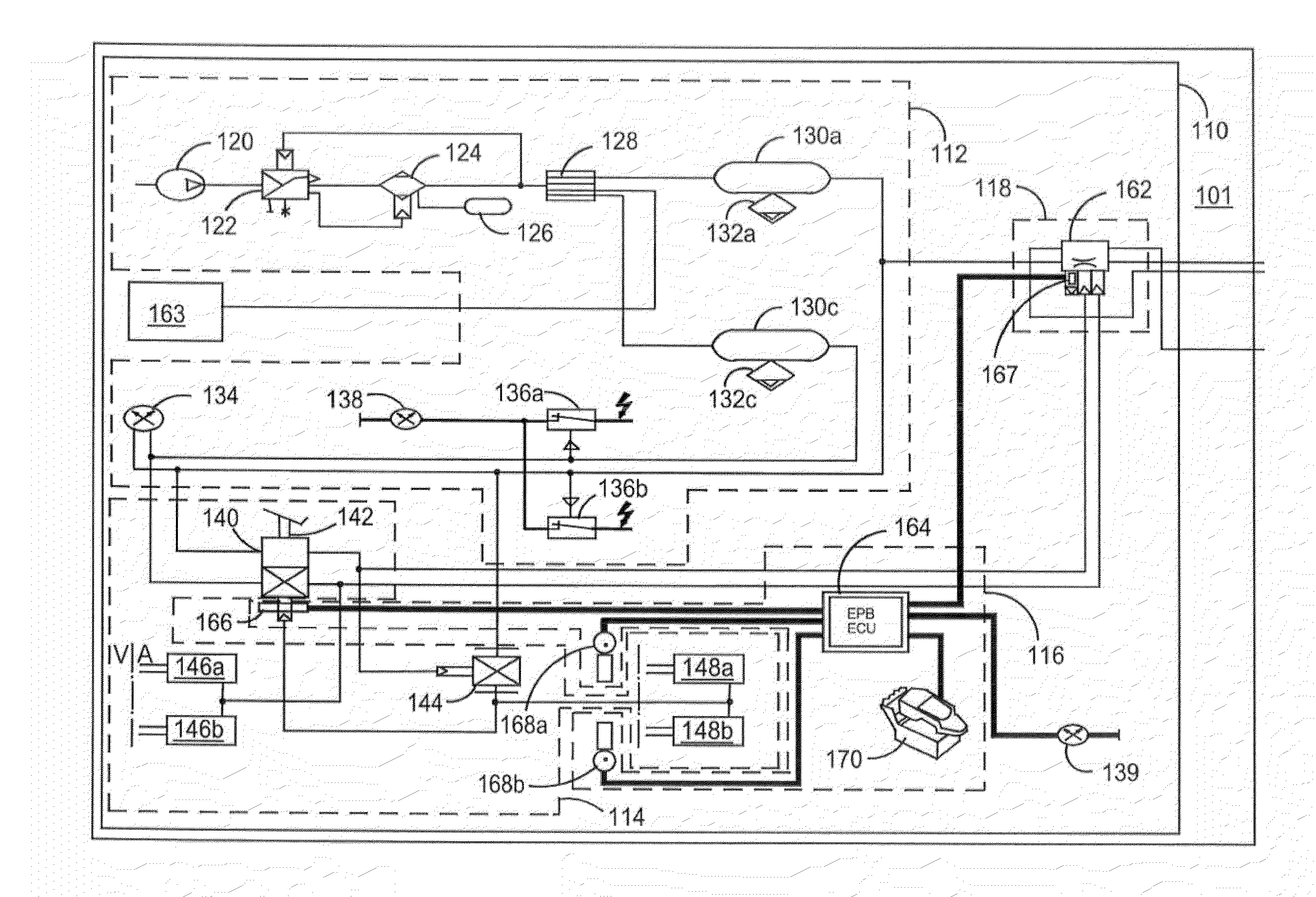
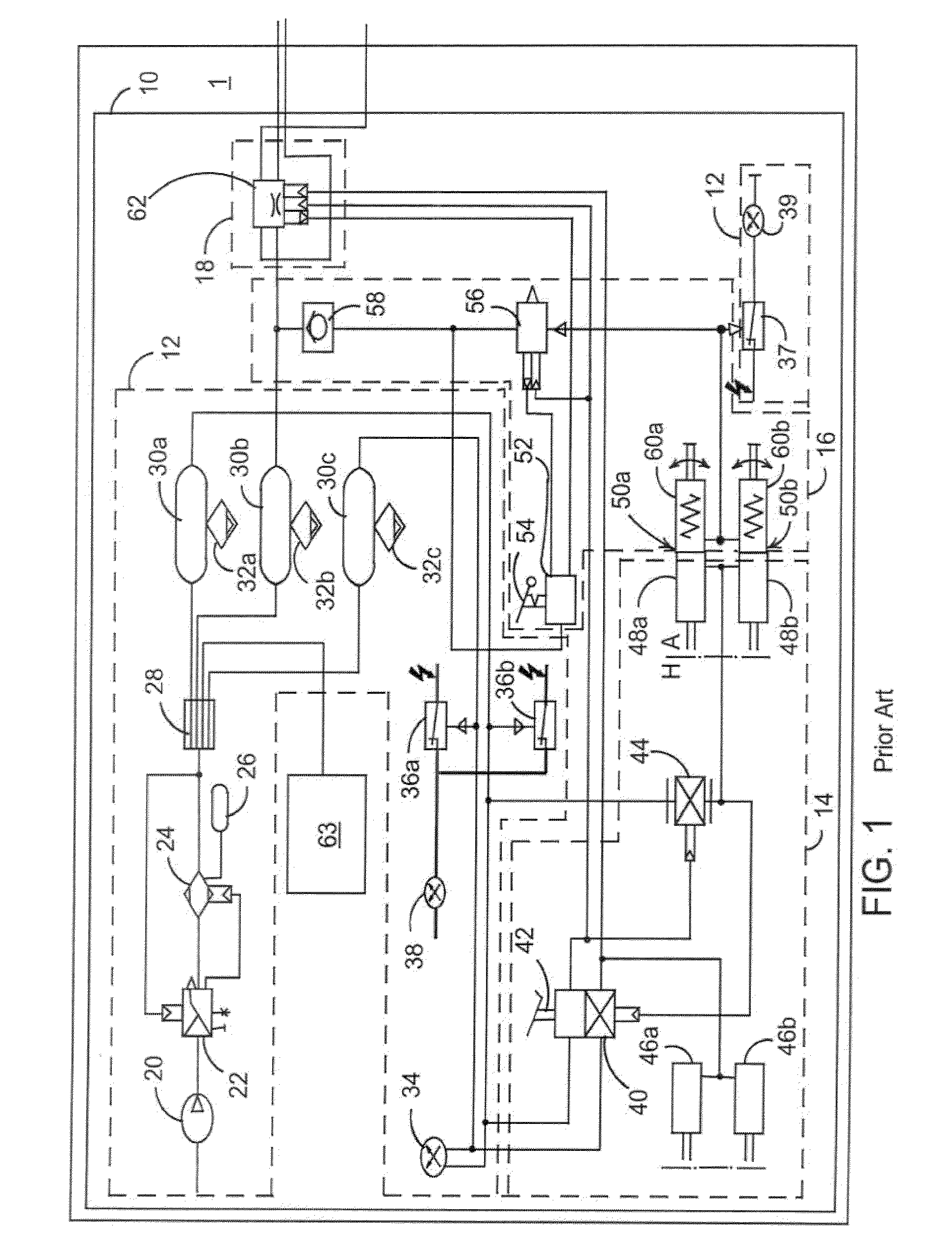
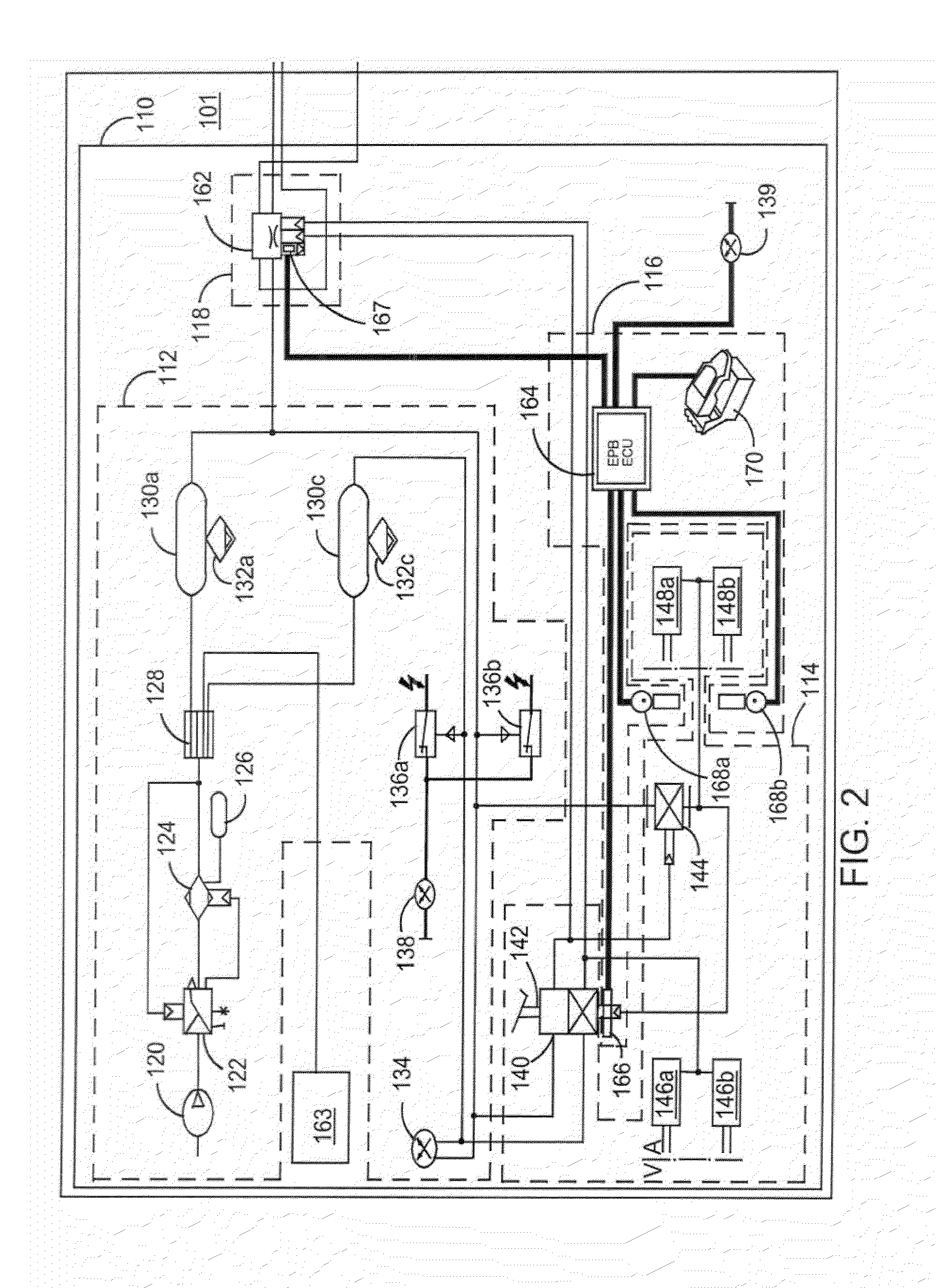
[0027]Referring to FIG. 1, a braking system 10 of a tractor unit 1 of an articulated truck is shown schematically. The system includes an air supply portion 12, a service brake portion 14, a parking brake portion 16, and a trailer control portion 18. The layout of such a system is well known to those skilled in the art, but for convenience, the prime components are briefly described below. The thinner connecting lines denote air connections, and the thicker connecting lines electrical connections.

[0028]The air supply portion 12 includes an air compressor 20 connected to a pressure regulator 22, an air dryer 24 having its own regeneration reservoir 26, a four circuit protection valve 28, and three air reservoirs 30a, 30b and 30c each with an associated water release valve 32a, 32b, and 32c. The supply lines from the air reservoirs 30a and 30c are further connected to a double pressure sensor 34. The double pressure sensor 34 enables the pressures in the supply lines from the two air...


PUM


Abstract

An electromechanical parking brake system for a heavy vehicle braked by air-actuated service brakes includes an EPB-ECU and a first electromechanical parking brake actuator controlled by the EPB-ECU. The electromechanical parking brake system further includes a redundant sub-system for applying a second parking brake in an event of a failure in the EPB-ECU or the first electromechanical parking brake actuator.

Description

REFERENCE TO RELATED APPLICATION[0001]This application claims priority to United Kingdom Patent Application No. 0802212.1 filed Feb. 6, 2008.BACKGROUND OF THE INVENTION[0002]The present invention relates generally to a brake system and method. More particularly, the present invention relates to a system configured to estimate a change in temperature of a brake component, a method of estimating the change in temperature of the brake component, and a system and method for applying a parking brake.[0003]Standard braking systems for heavy vehicles, such as trucks, buses and coaches, include air actuated service brakes at each wheel of the vehicle including a membrane type brake chamber biased into a brake off condition, and brakes operable as service and parking brakes on some wheels (e.g., the rear wheels of a tractor unit of an articulated truck and trailer unit). Such combined brakes also include a membrane type air chamber. Behind that, a parking brake chamber is biased into a parki...

Claims


Application Information

Patent Timeline
Patent Type & Authority Applications(United States)
IPC IPC(8): B60T13/10
CPCB60T7/122B60T8/1708B60T13/662Y10T477/82B60T17/221B60T2201/06B60T13/683B60T8/00B60T17/22F16D66/00B60T8/1837B60T8/24B60T7/107B60T13/746
Inventor JACKSON, JONATHAN LESLIE CHRISTOPHERWILDE, BRENDAN JOSEPHTAYLOR, MARTIN PORSLEITER, RALF
Owner MERITOR HEAVY VEHICLE BRAKING SYST (UK) LTD
Why Eureka
Try Eureka