Stator for an electric motor

a technology of electric motors and stators, applied in the field of electric motors, can solve the problems of inconvenient winding, low motor efficiency, and inconvenient winding methods, and achieve the effects of convenient winding, improved motor efficiency, and winding slot coils

Inactive Publication Date: 2009-08-06
JOHNSON ELECTRIC SA
View PDF18 Cites 22 Cited by
  • Summary
  • Abstract
  • Description
  • Claims
  • Application Information

AI Technical Summary

Benefits of technology

[0007]This is achieved in the present invention by using a stator core having separate teeth and yokes, eliminating the need for space for the winding tool. The use of a winding bobbin improves assembly efficiency and the insulation rating between he winding and the stator core which is important for high voltage applications.
[0011]Preferably, a detent structure is provided between each tooth and yoke interface, so as to limit movement of the teeth relative to the yokes in the radial direction.
[0019]The present invention allows the coils to be wound on a winding bobbin before assembling, so the winding is convenient in that the winding operation of each coil does not interfere with adjacent yokes and teeth. There is no need to keep comparatively large gaps between adjacent coils for the winding tool, so the winding slot coil ratio and the efficiency of the motor can be increased. There is no need to keep a comparatively large clearance between the inner ends of adjacent teeth for the winding tool to pass through, thus allowing cogging torque to be reduced. By separating the teeth and yokes the blank layout can be very compact allowing a high material utilization ratio.

Problems solved by technology

While winding the wires of the winding about the teeth, the winding tool needs to be shuttled continuously at the gap 5 between yoke 1 and teeth 3, and because of the limitation of the gap 5, the winding is very inconvenient and time-consuming.
The comparatively big gaps provided between the windings limit the slot coil ratio of the windings, thus the efficiency of the motor will be less than maximum.
However, the stator core produced by such T-shape lamination units still has disadvantages of inconvenient winding methods, low material utilization ratio, etc.

Method used


Image

  • Stator for an electric motor
  • Stator for an electric motor
  • Stator for an electric motor

Examples


Embodiment Construction

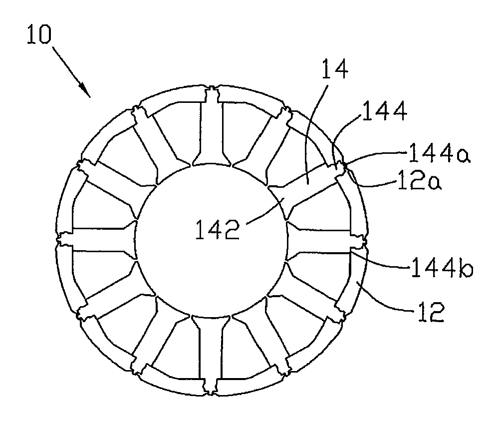
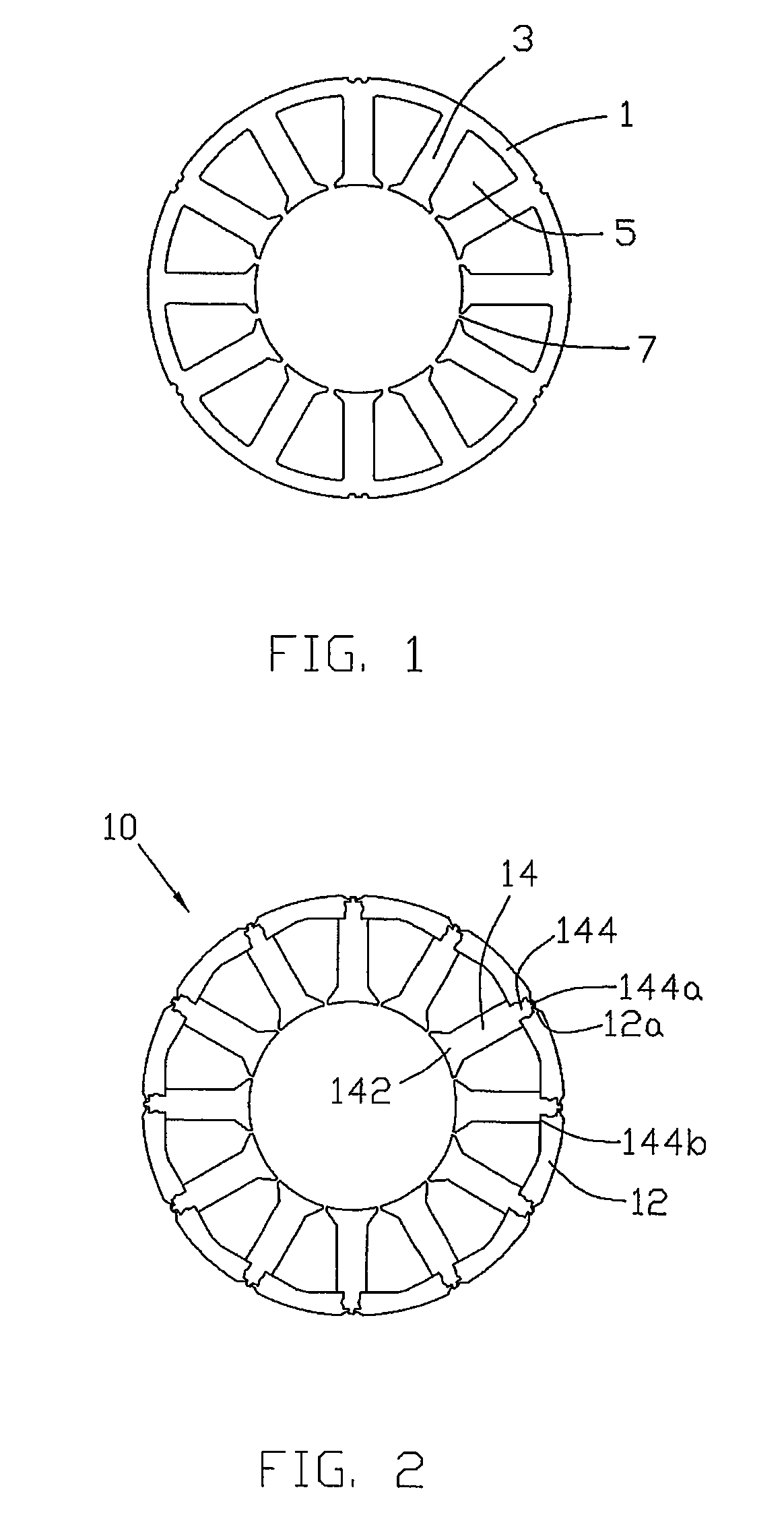
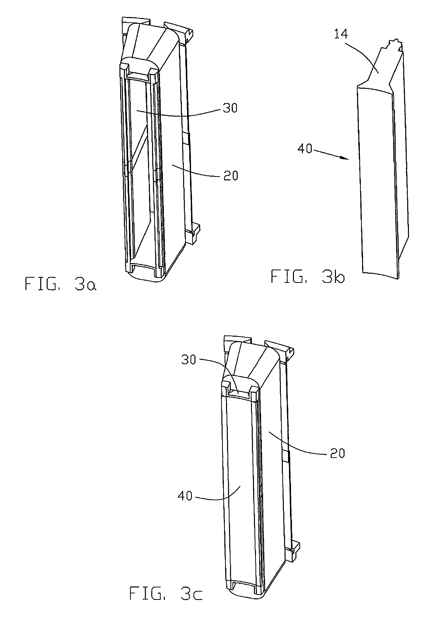
[0025]FIG. 2 is a plan view of a stator core lamination for a servo motor. The stator core 10 is a laminated structure with each layer of the stator lamination comprising a plurality of teeth lamination 14 and a plurality of yoke laminations 12 which extend between adjacent teeth laminations 14. Each yoke 50 as shown in FIG. 3e is formed by stacking together a plurality of yoke laminations 12 and each tooth 40 as shown in FIG. 3b is formed by stacking together a plurality of tooth laminations 14. The yoke laminations 12 are elongate and extend in the circumferential direction of the stator core 10 to form a radially outer portion of the core. The teeth laminations 14 extend in the radial direction. The yokes 50 and teeth 40 are thus separately formed. When assembled the yokes support the teeth and also provide the magnetic flux path between the teeth. One yoke 50 extends between each pair of adjacent teeth 40 and one tooth 40 is located between each pair of adjacent yokes 50. Each t...


PUM

PropertyMeasurementUnit
cylindrical shapeaaaaaaaaaa
angular speedaaaaaaaaaa
volumeaaaaaaaaaa

Abstract

A stator for an electric motor has a laminated stator core 10 formed from a plurality of stacked laminations, and a stator winding formed from a plurality of coils 20 wound on bobbins 30. The stator core 10 has a plurality of teeth 40 which extend radially and alternately spaced between and connected to circumferentially extending yokes 50. The yokes and the teeth are separately formed with each yoke 50 being a stack of yoke laminations 12 and each tooth 40 being a stack of tooth laminations 14. The teeth 40 are inserted through the bobbins 30 and arranged in a cylindrical form with each tooth 40 extending radially. Yokes 50 are then fixed between radially outer ends 144 of adjacent teeth to complete the radially outer portion of the stator core. Each tooth 40 has a radial location surface 144b which contacts an inner surface of the adjacent yokes 50. The yokes 50 and teeth 40 are fixed together by welding the yokes 50 to the outer ends 144 of the teeth 40.

Description

CROSS REFERENCE TO RELATED APPLICATIONS[0001]This non-provisional patent application claims priority under 35 U.S.C. §119(a) from Patent Application No. 200810065046.6 filed in The People's Republic of China on Jan. 11, 2009.FIELD OF THE INVENTION[0002]The present invention relates to an electric motor and in particular to a stator for an electric motor, especially a servo motor.BACKGROUND OF THE INVENTION[0003]A servo motor is one example of a motor having a salient pole wound stator. Usually, the stator poles, known as teeth because of their appearance, extend radially with a radially inner surface forming the pole face which is a discontinuous cylindrical surface, which confronts the rotor across a small air gap. The servo motor is commonly used with an electronic controller to provide angular displacement or angular speed in response to control signals. The servo motor has the advantage of having a small volume and light weight, high output power and torque, and being easy to co...

Claims


Application Information

Patent Timeline
Patent Type & Authority Applications(United States)
IPC IPC(8): H02K1/18H02K15/02
CPCH02K1/148Y10T29/49009H02K15/022
Inventor CHAI, JI DONGLIU, BAO TINGLI, WEN LIANGSHAO, ZHI DUAN
Owner JOHNSON ELECTRIC SA
Why Eureka
Try Eureka