Method of Reducing Common Mode Current Noise in Power Conversion Applications

a power conversion and common mode current technology, applied in the direction of power conversion systems, oscillation generators, pulse techniques, etc., can solve the problems of noise current flow, more problematic parasitic capacitance between the windings of the transformer, and common mode noise current, so as to reduce the isolation performance of the input side

Inactive Publication Date: 2009-08-06
TERADYNE
View PDF35 Cites 23 Cited by
  • Summary
  • Abstract
  • Description
  • Claims
  • Application Information

AI Technical Summary

Benefits of technology

[0024]Accordingly, a second aspect of the invention is the addition of common mode filtering components, a common mode choke 15, EMI plane 13 and capacitors 14, around the input side conditioning circuits 11 and first transformer 16. The common mode choke can be

Problems solved by technology

They are undesirable for several reasons including electromagnetic interference (EMI).
Common mode noise currents result from parasitic capacitance across the isolation barrier within the power conversion circuit.
Parasitic capacitance between the windings of the transformer is more problematic because close proximity is needed for magnetic coupling.
If the electrostatic coupling is not balanced perfectly, a common mode noise current will flow.
The primary drawback to this approach is the increased capacitance between transformer input and output.
General

Method used


Image

  • Method of Reducing Common Mode Current Noise in Power Conversion Applications
  • Method of Reducing Common Mode Current Noise in Power Conversion Applications
  • Method of Reducing Common Mode Current Noise in Power Conversion Applications

Examples


Embodiment Construction

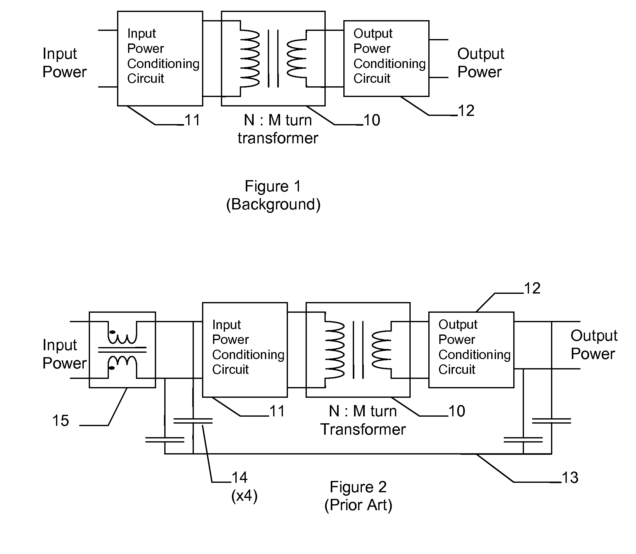
[0028]Common mode current noise filtering is a recognized as an essential element of compliance with regulatory requirements of electronic equipment. Filters similar in design to the prior art shown in FIG. 2 are especially common in systems containing isolated dc-dc power conversion circuits.

[0029]There are isolated power conversion applications, however, that can not tolerate the decrease in low frequency isolation inherent with these filters. The object of the present invention is to provide exceptional common mode current noise filtering and

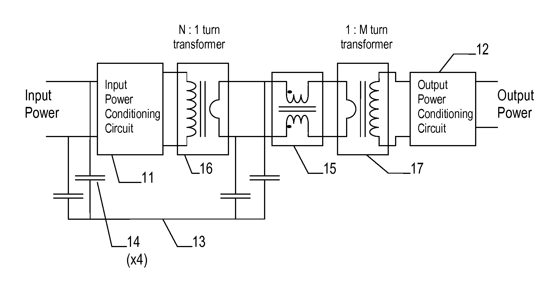
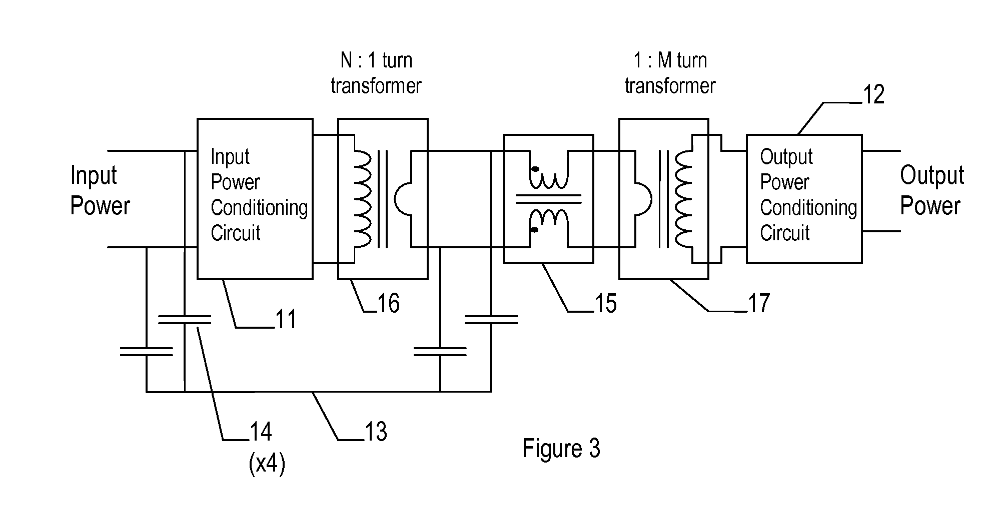
[0030]In relation to the prior art of FIG. 2, and in accordance with the present invention, a nominal isolation transformer 10 is separated into two transformers which would perform similar power conversion function, taking additional losses, if any, into account, if connected in series. In transformer terms, replacing an N:M turns ratio nominal transformer would require a N:1 turns ratio transformer and a 1:M turns ratio transformer. This ar...


PUM


Abstract

A transformer and filter circuit for reducing common mode noise current in isolated power conversion circuits, comprising a series connection of: a first transformer having an N:1 turns ratio, a common mode current filter, and a second transformer having a 1:M turns ratio. The overall effect being a transformer with N:M turns ratio and with low capacitive coupling from the primary N turns to the secondary M turns thus providing a high impedance to common mode currents crossing the isolation. The series connection of two transformers allows one to be bridged with additional common mode filter components without significant reduction in isolation impedance.

Description

CROSS-REFERENCE TO RELATED APPLICATIONS[0001]Not ApplicableSTATEMENT REGARDING FEDERALLY SPONSORED RESEARCH OR DEVELOPMENT[0002]Not ApplicableREFERENCE TO SEQUENCE LISTING, A TABLE, OR A COMPUTER PROGRAM LISTING COMPACT DISK APPENDIX[0003]Not ApplicableBACKGROUND OF THE INVENTION[0004]U.S. C1. 318 / 254, 671, 327 / 552, 336 / 200, 223, 232, 363 / 39, 40, 47, 48REFERENCESU.S. Patent Documents[0005]5,990,776November 1999Jitaru336 / 2006,208,098 B1March 2001Kume et al.318 / 2546,377,479 B1April 2002Ayano et al.363 / 406,490,181 B1December 2002Liu et al.363 / 406,583,682 B1June 2003Dubhashi et al.333 / 126,636,107 B2October 2003Pelly327 / 5526,788,558 B2September 2004Pelly363 / 406,794,929 B2September 2004Pelly327 / 5526,842,069 B2January 2005Takahashi et al.327 / 5526,879,500 B2April 2005Liu et al.363 / 406,898,092 B2May 2005Briere et al.363 / 396,927,665 B2August 2005Nakatsu et al.336 / 2006,980,074 B1December 2005Jitaru336 / 2007,038,899 B2May 2006Hsu et al.361 / 1187,078,988 B2July 2006Suzuki et al.333 / 1817,292,126 B2...

Claims


Application Information

Patent Timeline
IPC IPC(8): H04B1/10
CPCH02M7/48H04B15/02H02M2001/123H02M1/123
Inventor BOWHERS, WILLIAM J.
Owner TERADYNE
Why Eureka
Try Eureka