Dual-band multi-polarization common-caliber waveguide slot antenna

A waveguide slot antenna and vertically polarized antenna technology is applied in slot antennas, antennas, and devices that make antennas work in different frequency bands at the same time, which can solve the problems of low antenna efficiency, high cross-polarization, and low isolation, and achieve High power capacity, low cross-polarization, weight reduction effect

Active Publication Date: 2015-04-29
CHINA ELECTRONIC TECH GRP CORP NO 38 RES INST
View PDF14 Cites 16 Cited by
  • Summary
  • Abstract
  • Description
  • Claims
  • Application Information

AI Technical Summary

Problems solved by technology

[0006] However, these dual-band multi-polarization antennas mentioned above basically use microstrip patch antennas. The disadvantages of

Method used


Image

  • Dual-band multi-polarization common-caliber waveguide slot antenna
  • Dual-band multi-polarization common-caliber waveguide slot antenna
  • Dual-band multi-polarization common-caliber waveguide slot antenna

Examples


Embodiment 1

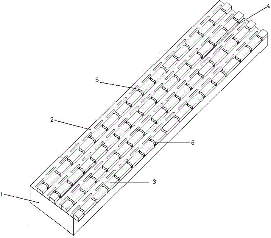
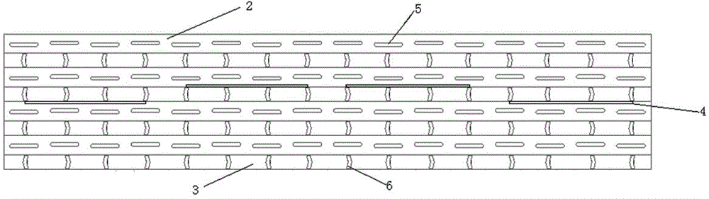
[0044] see figure 1 , figure 2 , image 3 , a dual-band multi-polarized co-aperture waveguide slot antenna includes L-band vertically polarized antennas, C-band vertically polarized antennas, and C-band horizontally polarized antennas with equal lengths; the C-band vertically polarized antenna is C-band vertically polarized Waveguide slot antenna; C-band horizontally polarized antenna is a C-band horizontally polarized waveguide slot antenna.

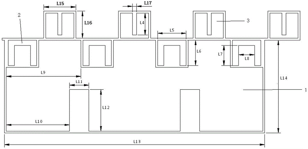
[0045] see Image 6 , the L-band vertically polarized antenna consists of a double-ridged waveguide 1 with a first broadside radiation longitudinal slot and a first coaxial connector 7; the two ridges of the double-ridged waveguide 1 are located on both sides of the centerline of the waveguide, and The distances between the center lines are equal; the top of the double-ridge waveguide 1 is evenly distributed with four first broadside radial longitudinal slots 4, and the first coaxial connector 7 is installed at the bottom center of ...

Embodiment 2

[0060] see figure 1 , Image 6 , Figure 10 , a dual-band multi-polarization co-aperture antenna array working in L-band and C-band. The L-band antenna consists of a waveguide slot antenna line array with 1×4 elements. The C-band dual-polarized antenna consists of a waveguide slot antenna array with 4×16 elements, and the antenna array is composed of four C-band waveguide slot linear arrays. Each unit line array consists of 16 slots. The waveguide of the L-band antenna is located below the waveguide of the C-band dual-polarized antenna. In this embodiment, the spacing of the L-band antenna slots is L1=0.5 like Image 6 shown. The element spacing between C-band vertically polarized antenna arrays Ld2=0.7 like Image 6 As shown, the element spacing Ld3=0.7 between the C-band horizontally polarized antenna arrays like Figure 10 As shown, this sub-array is connected with T / R components, supplemented by power supply, wave control and installation structural parts, etc...


PUM


Abstract

The invention relates to a dual-band multi-polarization common-caliber waveguide slot antenna which comprises an L-band vertical polarization antenna, a C-band vertical polarization antenna and a C-band horizontal polarization antenna, which are equal in length and are waveguide slot antennas. The C-band vertical polarization antenna and the C-band horizontal polarization antenna form a C-band dual-polarization antenna array which is positioned at the upper part, and the L-band vertical polarization antenna is positioned at the lower part; the L-band vertical polarization antenna, the C-band vertical polarization antenna and the C-band horizontal polarization antenna feed at an antenna waveguide tube center through a coaxial connector, and the coaxial connector and a waveguide tube form a 3dB power divider. The exciting effect on the L-band vertical polarization antenna, the C-band vertical polarization antenna and the C-band horizontal polarization antenna is realized. The dual-band multi-polarization common-caliber waveguide slot antenna realizes sharing of a plurality of waveguide slot antennas on the same physical caliber area. Compared with a dual-band multi-polarization micro-strip common-caliber antenna, the antenna has the advantages of being high in efficiency, high in polarization isolation, low in cross polarization and high in power capacity.

Description

technical field [0001] The invention belongs to the technical field of antennas, in particular to a dual-band multi-polarization common-aperture antenna, in particular to a dual-frequency band multi-polarization common-aperture antenna composed of three metal radiation waveguides. The invention can be used for both reception and transmission of radio waves. In military terms, it can be used as a terminal antenna for phased array radar systems. In civilian use, it can be used as a spaceborne radar antenna, weather radar antenna, etc. Background technique [0002] With the rapid development of applications and demands, on the one hand, there are more and more electronic devices working at various frequencies; , Efficiency and other electrical performance indicators have put forward more and more stringent requirements, especially in the radar system, the antenna occupies a large proportion, so it is necessary to reduce the weight, compress the profile, improve the antenna ef...

Claims


Application Information

Patent Timeline
IPC IPC(8): H01Q13/10H01Q5/10
Inventor 陈明汪伟鲁加国张洪涛金谋平
Owner CHINA ELECTRONIC TECH GRP CORP NO 38 RES INST
Why Eureka
Try Eureka