Optical position measuring arrangement

a technology of optical position and measuring arrangement, applied in the direction of measuring devices, converting sensor output optically, instruments, etc., can solve the problems of increased susceptibility, no more suitable structured photo diodes are available, etc., and achieve the effect of high degree of effectiveness

Active Publication Date: 2009-08-06
DR JOHANNES HEIDENHAIN GMBH
View PDF19 Cites 14 Cited by
  • Summary
  • Abstract
  • Description
  • Claims
  • Application Information

AI Technical Summary

Benefits of technology

[0007]It is an object of the present invention to disclose an optical position measuring arrangement which makes possible the dependable detection of fine fringe patterns in a scanning plane with a high degree of effectiveness and as great as possible an insensitivity to dirt on the measurement grating.

Problems solved by technology

No more suitable structured photo diodes are available below a fringe pattern period of approximately 40 μm.
The known variation in EP 724 713 B1 is disadvantageous because of an increased susceptibility of the measurement grating to dirt, in particular linearly-shaped dirt deposits extending along the measuring direction, as well as to inhomogeneities in the measurement grating, for example scratches.

Method used


Image

  • Optical position measuring arrangement
  • Optical position measuring arrangement
  • Optical position measuring arrangement

Examples


first embodiment

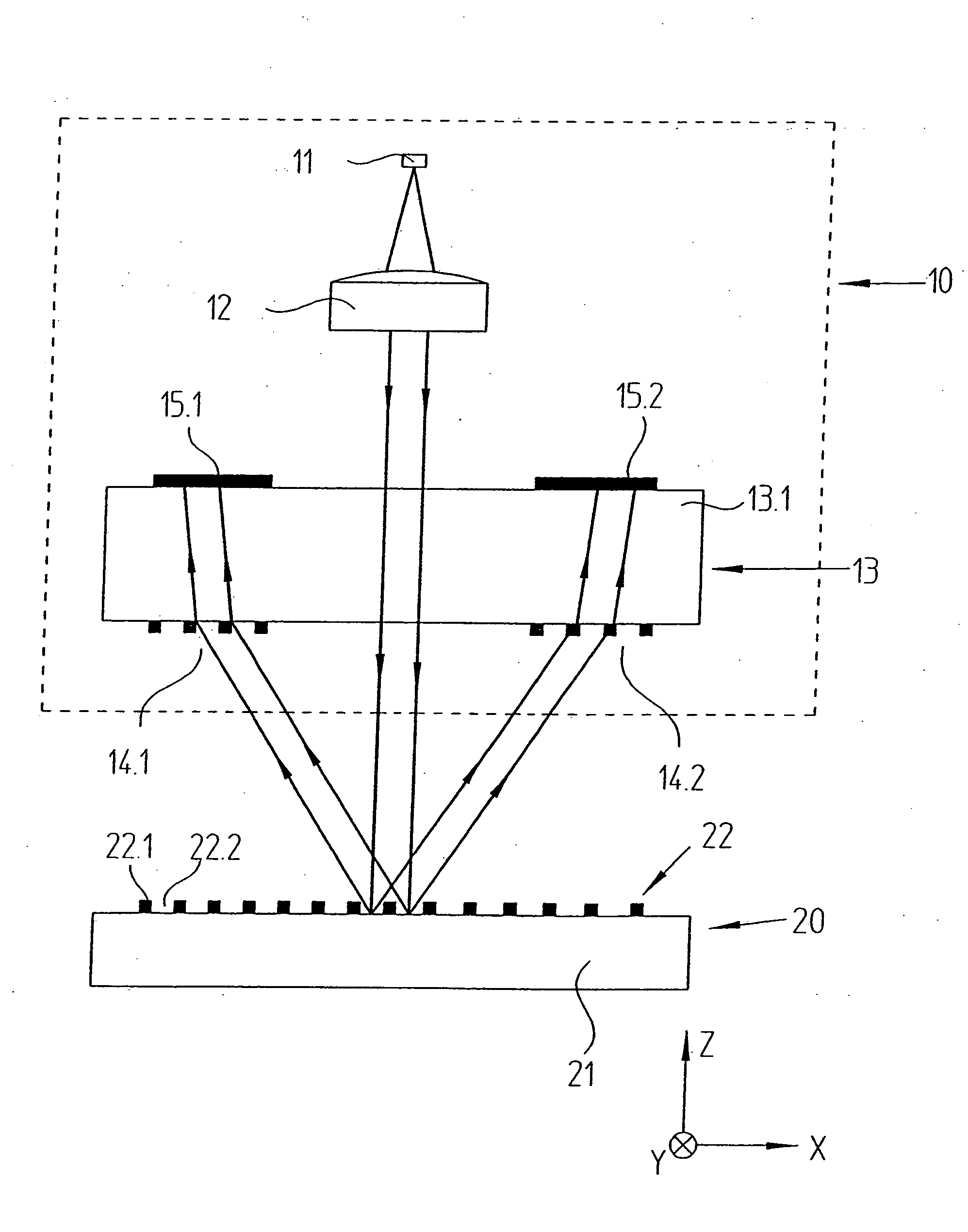
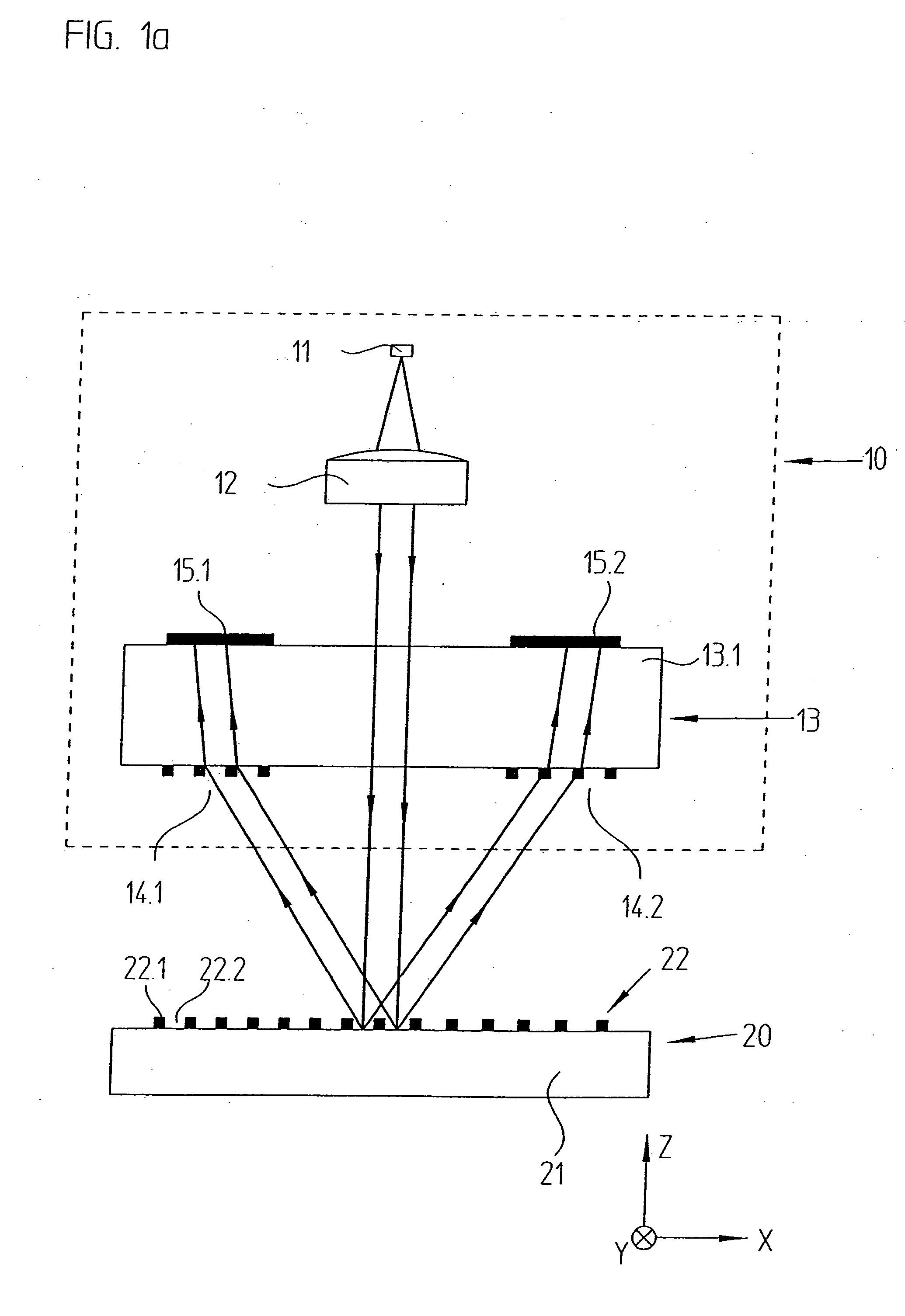
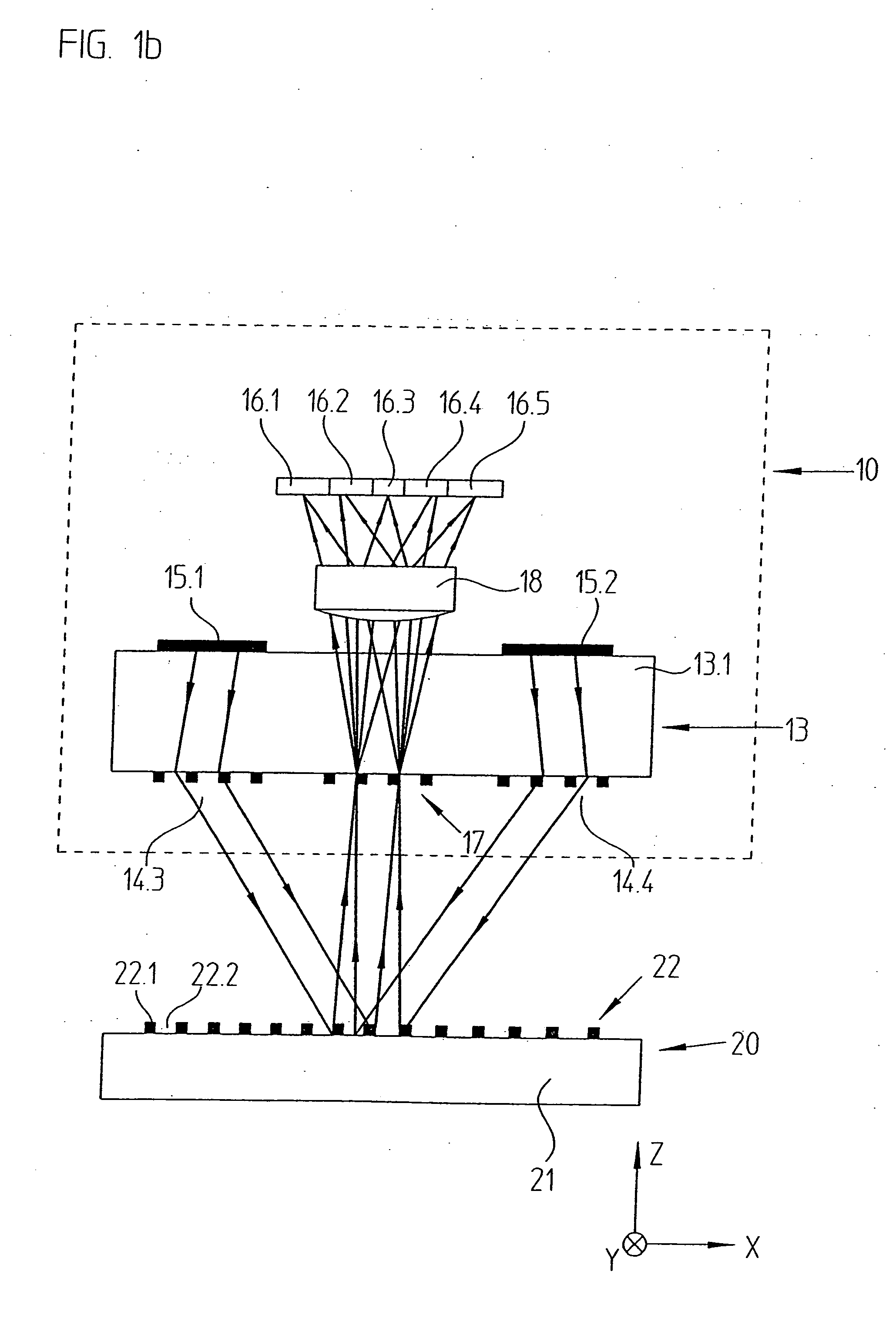
[0048]the position measuring arrangement in accordance with the present invention, in particular the scanning grating employed there, will be explained in what follows by FIGS. 1a to 1d. Here, FIGS. 1a and 1b show, each in a schematic view, partial scanning beam paths in a lateral plan view in the x, z-plane. The scanning beam path from the light source 11 up to the impingement of the partial beam bundles on the reflector elements 15.1, 15.2 is represented in FIG. 1a. FIG. 1b shows the scanning beam path from the impingement of the partial beam bundles on the reflector elements 15.1, 15.2 up to the detector elements 16.1 to 16.5. FIGS. 1c and 1d show partial plan views of the scanning grating 17 and of the detector plane of this exemplary embodiment.

[0049]In this example, the position measuring arrangement in accordance with the present invention includes a measurement grating 20, designed as a reflection measurement grating, as well as a scanning unit 10, which is movable with resp...

second embodiment

[0079]In the case of this exemplary embodiment, as can be seen in FIG. 2a, the structured elements of the scanning grating 170 are all aligned parallel in the position measuring arrangement, or perpendicularly in relation to the other gratings, in particular in relation to the measurement grating, whose structured elements also extend in the y-direction and are arranged periodically along the measuring direction x. A design of the scanning grating 170 has been shown to be advantageous in which a so-called VCSEL (vertical cavity surface-emitting laser) light source is employed. Since so-called polarization jumps sometimes occur in such light sources, these are preferably arranged in such a way that the main polarization axes of the VCSEL light source assume the angles + / −45° in relation to the structural elements of the measurement graduation on the measurement grating. The connection with the scanning plate 170 is assured in that incremental signals, which are phase-shifted by 180°,...

third embodiment

[0081]a scanning grating 270 will be explained in what follows by FIGS. 3a and 3b, which again represent partial plan views of the scanning grating 270, as well as of the detector plane with detector elements 260.1 to 260.6 placed there. Such a scanning grating 270 could also be employed for example in a position measuring arrangement such as has been explained by the scanning beam path in FIGS. 1a and 1b. In contrast to the two variants described above, the third exemplary embodiment of a scanning grating 270 is suitable for a three-grating system, in which three phase-shifted incremental signals S—0°, S—120° and S—240° are generated in the position measuring arrangement in accordance with the present invention; the above mentioned value n has now been selected to be n=3.

[0082]In this embodiment, the scanning grating 270 includes three different grating sections 270.1 to 270.3, which are arranged in blocks with the fringe pattern period TPS along the measuring direction x, wherein ...


PUM


Abstract

An optical position measuring arrangement for the generation of n>1 phase-shifted incremental signals characterizing relative positions of two objects which are movable with respect to each other along a measuring direction. The optical position measuring arrangement includes a light source that emits bundles of beams, a measurement grating, a plurality of optional gratings and a scanning unit. The scanning unit includes a scanning grating arranged in a scanning plane, wherein the scanning grating includes a plurality of blocks arranged periodically along the measuring direction with a scanning grating periodicity TPAG equaling a fringe pattern periodicity TPS, and each block includes n grating sections (n=1, 2, 3, . . . ) of a width bx=TPAG/n, exclusively arranged along the measuring direction, and each of the n grating sections has a periodic grating structure, which causes a deflection of the bundles of beams propagated through each of the n grating sections in several spatial directions, in which resulting spatial directions of the n grating sections in a block differ. The scanning unit further includes a plurality of detector elements arranged downstream of the scanning grating, wherein the detector elements are arranged in the spatial directions in the detector plane, and wherein the detector plane is located in an area in which the bundles of beams coming from the scanning grating are completely spatially separated. The fringe pattern having a periodicity TPS is formed in the scanning plane by an interaction of the bundles of beams emitted by the light source with the measurement grating and the further optional gratings.

Description

RELATED APPLICATIONS[0001]Applicants claim, under 35 U.S.C. § 119, the benefit of priority of the filing date of Feb. 2, 2008 of a German patent application, copy attached, Serial Number 10 2008 007 319.9, filed on the aforementioned date, the entire contents of which is incorporated herein by reference.BACKGROUND[0002]1. Technical Field[0003]The present invention relates to an optical position measuring arrangement for generating n>1 phase-shifted, shift-dependent incremental signals in relation to two objects which are movable with respect to each other along a measuring direction (x), and includes a measurement grating and a scanning unit having a scanning grating arranged in the scanning plane, as well as several detector units arranged downstream of the scanning grating, from which a fringe pattern of the fringe pattern periodicity TPS results in the scanning plane because of the interaction of the bundles of beams emitted by a light source with the measurement grating and f...

Claims


Application Information

Patent Timeline
Patent Type & Authority Applications(United States)
IPC IPC(8): G01B11/14
CPCG01D5/38
Inventor HERMANN, MICHAELSANDIG, KARSTEN
Owner DR JOHANNES HEIDENHAIN GMBH
Why Eureka
Try Eureka