License plate lamp

a technology of license plate lamps and light beams, which is applied in the manufacture of electric discharge tubes/lamps, electrode systems, lighting and heating apparatuses, etc., can solve the problems of low light utilization efficiency, and increase manufacturing costs, so as to improve light utilization efficiency and reduce manufacturing costs of license plate lamps. , the effect of light utilization efficiency

Inactive Publication Date: 2009-08-06
KOITO MFG CO LTD
View PDF6 Cites 11 Cited by
  • Summary
  • Abstract
  • Description
  • Claims
  • Application Information

AI Technical Summary

Benefits of technology

[0023]The light emitted by the light emitting diode is thus controlled by the control lens so as to be radiated toward the surface of the license plate without using a reflector. The light utilization efficiency can, therefore, be improved.
[0024]Moreover, since the light utilization efficiency can be improved without providing a large reflector, the manufacturing cost of the license plate lamp can be reduced accordingly.
[0025]In one or more embodiments of the invention, the license plate lamp includes a diffusion lens for diffusing in the vertical direction the light emitted by the light emitting diode and received through the control lens and radiating the diffused light toward the license plate. Variation in luminance on the surface of the license plate can therefore be reduced, whereby uniformity of luminance can be assured.

Problems solved by technology

Since there is a limit to the reflection efficiency of the reflector, there is a problem of low light utilization efficiency accordingly.
However, increasing the reflector size will cause problems such as increase in manufacturing cost and increase in size of a license plate lamp.
Moreover, light control (light distribution control) using a reflector requires high processing accuracy of the reflective surface of the reflector.
However, increasing the processing accuracy will increase the manufacturing cost accordingly.

Method used


Image

  • License plate lamp
  • License plate lamp
  • License plate lamp

Examples


Embodiment Construction

[0041]Hereinafter, embodiments of a license plate lamp in accordance with the present invention will be described with reference to accompanying drawings.

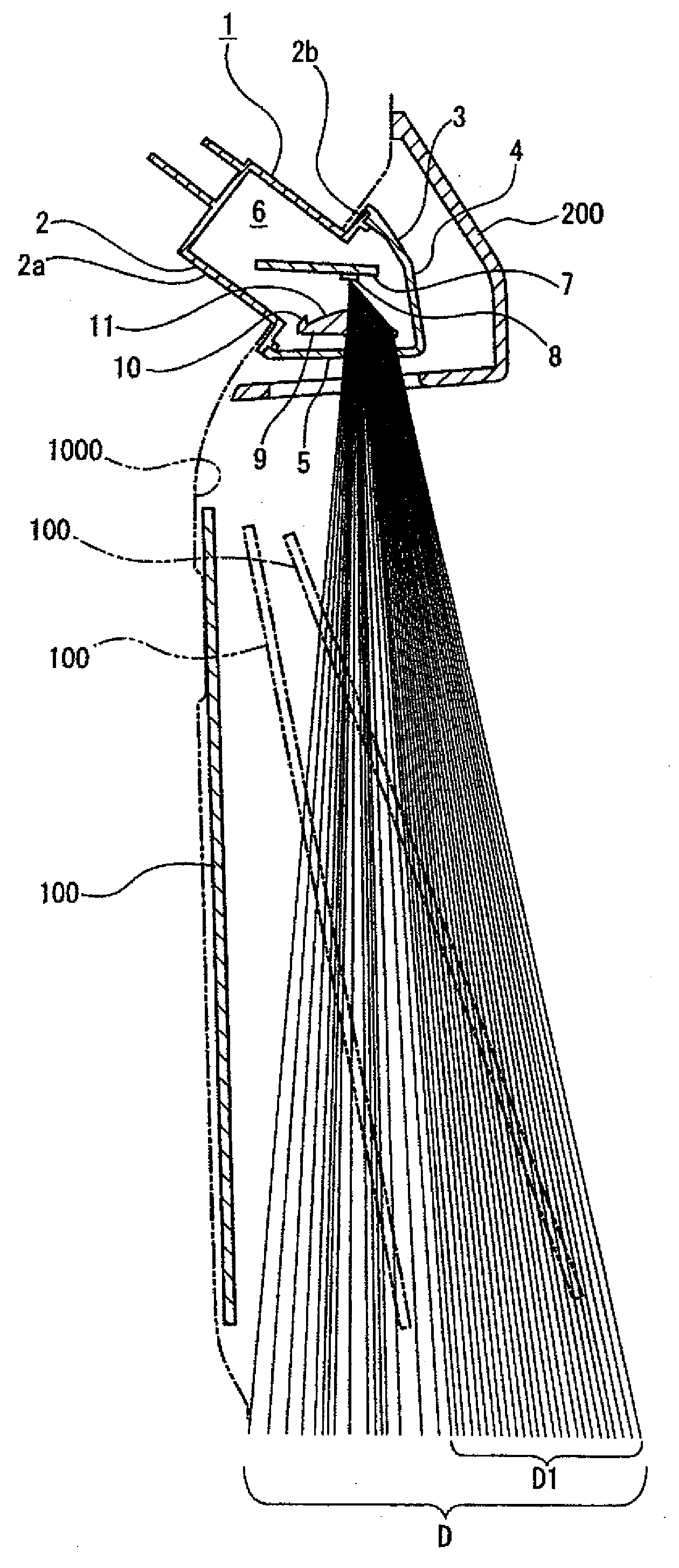
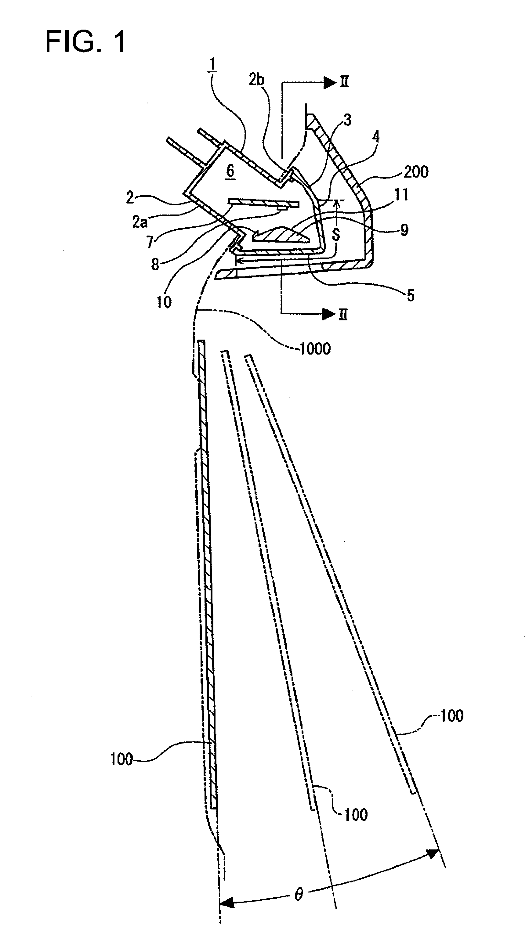
[0042]A license plate 100 irradiated with light by a license plate lamp 1 is attached to a rear end of a vehicle body 1000 (see FIG. 1). The license plate 100 is formed in a horizontally long flat-plate shape and is tilted at a predetermined angle with respect to a vertical direction. The tilt angle of the license plate 100 varies depending on, for example, the type of vehicle to which the license plate 100 is attached, and is in a range θ shown in FIG. 1.

[0043]The license plate lamp 1 is attached to the rear end of the vehicle body 1000 and is located above the license plate 100. The license plate lamp 1 is covered from the rear side by a shielding cover 200 attached to the rear end of the vehicle body 1000 so that light is radiated only in a downward direction.

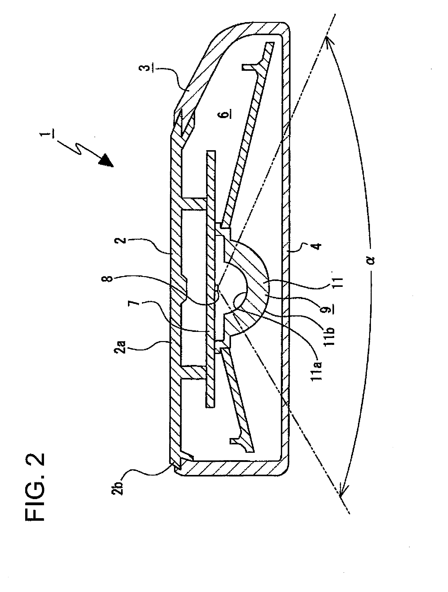
[0044]The license plate lamp 1 is formed in a horizontally long flat-p...


PUM


Abstract

A license plate lamp for radiating light to a surface of a license plate attached to a rear end of a vehicle body includes: a lamp body disposed above the license plate; a light emitting diode disposed within the lamp body, the light emitting diode having an optical axis extending in a vertical direction for emitting light toward a license plate located under the light emitting diode; and a control lens provided between the light emitting diode and the license plate for controlling the light emitted by the light emitting diode so that the light is radiated toward a surface of the license plate. The control lens includes a first control portion for radiating the light emitted by the light emitting diode toward an upper end part of the surface of the license plate, and a second control portion located rearward of the first control portion for radiating the light emitted by the light emitting diode toward substantially a whole region of the surface of the license plate.

Description

BACKGROUND OF INVENTION[0001]1. Field of the Invention[0002]The present invention relates to a license plate lamp. More particularly, the present invention relates to achieving improvement of light utilization efficiency and the like by providing a control lens for controlling light emitted by a light emitting diode so that the light is radiated to the surface of a license plate.[0003]2. Related Art[0004]There have been license plate lamps for radiating light toward the surface of a license plate attached to a rear end of a vehicle body.[0005]An example of such a license plate lamp is a license plate lamp using an incandescent bulb as a light source. However, incandescent bulbs have problems such as short life and high power consumption.[0006]Accordingly, there has been recently proposed a license plate lamp using a light emitting diode (LED) as a light source instead of an incandescent bulb (e.g., see Patent Document 1). Light emitting diodes have longer life, smaller size, and low...

Claims


Application Information

Patent Timeline
Patent Type & Authority Applications(United States)
IPC IPC(8): B60Q1/56H01J9/24F21W107/10
CPCB60Q1/56B60R13/10
Inventor KOIZUMI, HIROYA
Owner KOITO MFG CO LTD
Why Eureka
Try Eureka