Abnormality diagnosis device of internal combustion engine

a technology of abnormality diagnosis and internal combustion engine, which is applied in the direction of electrical control, process and machine control, instruments, etc., to achieve the effect of suppressing the fluctuation of the torque due to the difference in the fuel spray form between the cylinders of the internal combustion engin

Active Publication Date: 2009-08-06
DENSO CORP
View PDF3 Cites 30 Cited by
  • Summary
  • Abstract
  • Description
  • Claims
  • Application Information

AI Technical Summary

Benefits of technology

[0018]Therefore, according to another aspect of the present invention, the abnormality diagnosing section gradually changes the ratio between the command injection quantities of the plurality of injectors in the injection ratio changing control. With such the construction, the torque shock can be suppressed by inhibiting the sudden change in the combustion state due to the injection ratio changing control. As a result, the deterioration of the drivability can be prevented.
[0039]With such the construction, when certain one of the multiple injectors of the cylinder becomes abnormal, the fuel can be injected through the injectors in the same positions in all the cylinders. Accordingly, a fuel spray form (i.e., a forming state of a mixture gas) of the cylinder having the abnormal injector can be prevented from differing from the fuel spay forms of the other cylinders and the fuel spray forms of all the cylinders can be equalized to each other. As a result, the torque fluctuation due to the difference in the fuel spray form among the cylinders of the internal combustion engine can be suppressed.

Problems solved by technology

If the injection ratio changing control is performed under the same condition, a changing behavior of the actual sum injection quantity of the multiple injectors varies and therefore a changing behavior of the output of the exhaust gas sensor varies depending on which one of the multiple injectors is abnormal.

Method used


Image

  • Abnormality diagnosis device of internal combustion engine
  • Abnormality diagnosis device of internal combustion engine
  • Abnormality diagnosis device of internal combustion engine

Examples


first embodiment

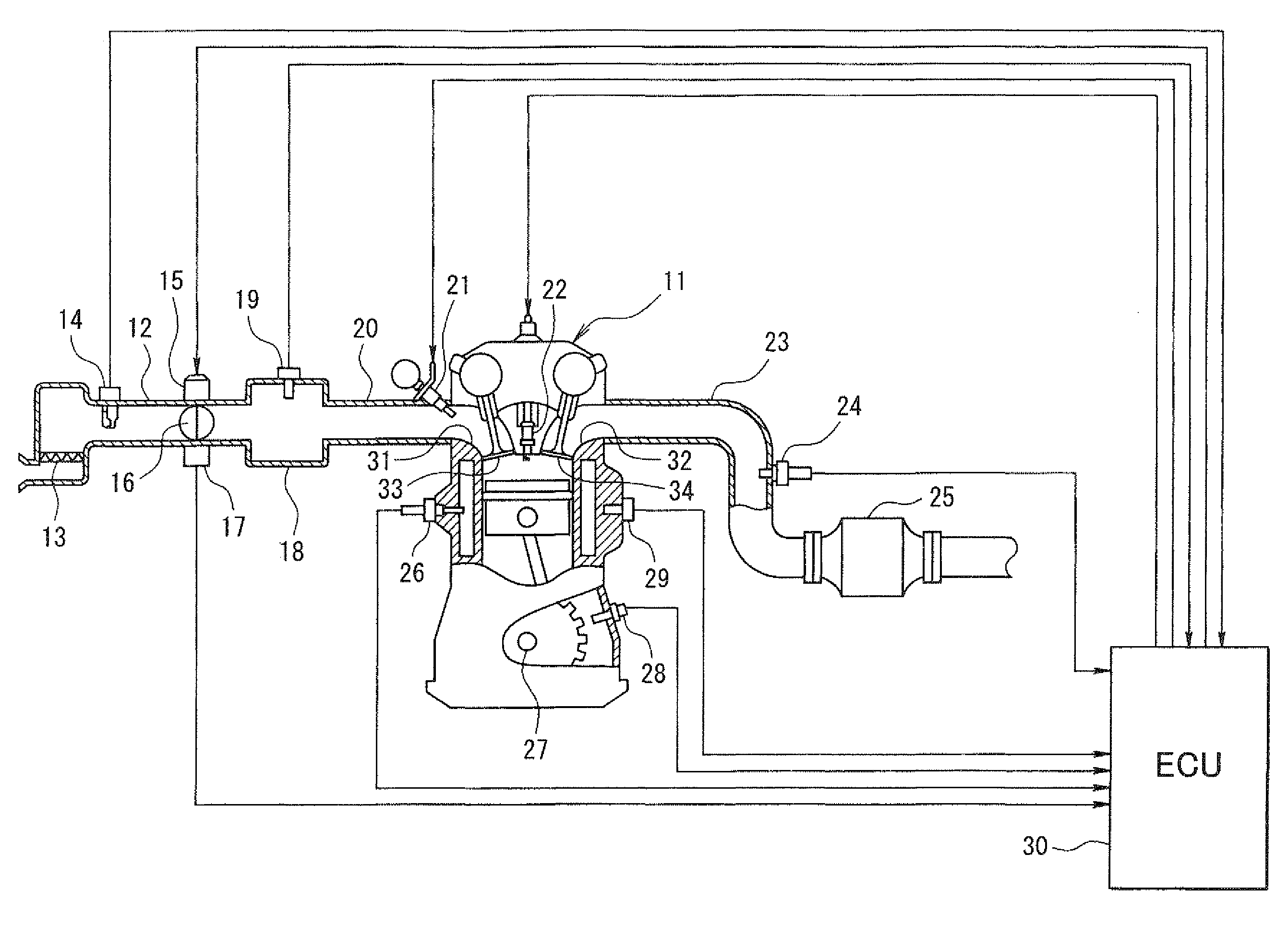
[0056]First, the present invention will be described with reference to FIGS. 1 to 7. First, a general configuration of an entire engine control system will be explained with reference to FIG. 1.

[0057]An air cleaner 13 is provided in the most upstream portion of an intake pipe 12 of an engine 11 (an internal combustion engine). An airflow meter 14 for sensing an air intake quantity is provided downstream of the air cleaner 13. A throttle valve 16, whose opening degree is regulated by a motor 15, and a throttle position sensor 17 for sensing an opening degree (a throttle opening degree) of the throttle valve 16 are provided downstream of the airflow meter 14.

[0058]A surge tank 18 is provided downstream of the throttle valve 16, and an intake pipe pressure sensor 19 for sensing intake pipe pressure is provided to the surge tank 18. An intake manifold 20 for introducing the air into each cylinder of the engine 11 is provided to the surge tank 18. An injector 21 for injecting fuel is pro...

second embodiment

[0094]In the second embodiment, an injector abnormality diagnosis routine of FIGS. 8 and 9 explained in detail later is performed. Thus, when the lean-side abnormality or the rich-side abnormality of the air-fuel ratio occurs, the injection ratio changing control is performed on respective cylinders in series one by one. Thus, abnormal cylinder diagnosis for specifying the lean-side abnormality cylinder or the rich-side abnormality cylinder and abnormal injector diagnosis for specifying the abnormal injector 21 are performed.

[0095]In the injector abnormality diagnosis routine shown in FIGS. 8 and 9, it is determined first in S201 whether the lean-side abnormality of the air-fuel ratio has occurred. When it is determined that the lean-side abnormality of the air-fuel ratio has occurred, it is determined that the lean-side abnormality has occurred in the injector 21 of certain one of the cylinders. Then, the injection ratio changing control is performed on the respective cylinders in ...

third embodiment

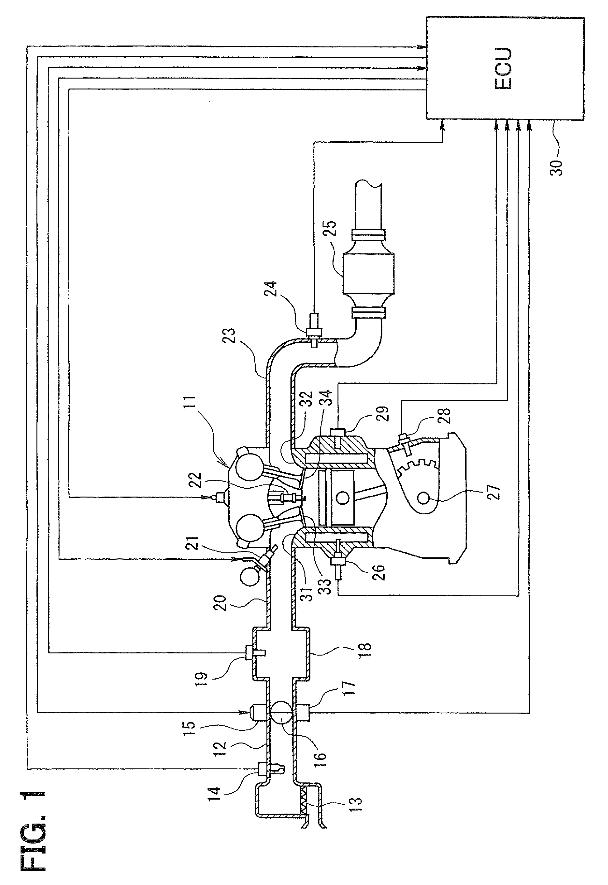
[0126]According to the above-described third embodiment, when the abnormality diagnosis of the injectors 21 (A, B) is performed, the two injectors 21 of each cylinder are caused to perform the injection in a switched manner in turn, and the existence or nonexistence of the torque fluctuation (or the fluctuation of the combustion state) is determined. The abnormal injector 21 is specified out of the two injectors 21 based on the determination result. Accordingly, when the abnormality occurs in either one of the injectors 21, the abnormal injector 21 can be specified.

[0127]Moreover, in the present embodiment, when the abnormality occurs in either one of the injectors 21, the injection operation of the injector 21 determined to be abnormal is prohibited and the increase correction of the injection quantity of the remaining injector 21 is performed, thereby injecting the fuel quantity equivalent to the required injection quantity only by the remaining injector 21. Thus, even when either...


PUM


Abstract

A cylinder causing an abnormal air-fuel ratio is specified. Injection ratio changing control for gradually changing a ratio between command injection quantities of two injectors of the abnormal cylinder while keeping the sum of the command injection quantities of the two injectors constant is performed on the abnormal cylinder. If the injection ratio changing control is performed under the same condition, a changing behavior of the actual sum injection quantity of the two injectors varies and a changing behavior of the air-fuel ratio varies depending on which one of the two injectors is abnormal. Therefore, the abnormal injector out of the two injectors is specified using a learning value of an air-fuel ratio feedback correction value based on an output of an exhaust gas sensor.

Description

CROSS REFERENCE TO RELATED APPLICATIONS[0001]This application is based on and incorporates herein by reference Japanese Patent Applications No. 2008-20827 filed on Jan. 31, 2008 and No. 2008-27991 filed on Feb. 7, 2008.BACKGROUND OF THE INVENTION[0002]1. Field of the Invention[0003]The present invention relates to an abnormality diagnosis device of an internal combustion engine provided with multiple injectors for each cylinder of the internal combustion engine.[0004]2. Description of Related Art[0005]As described in Patent document 1 (JP-A-2006-299945), there is a system that is provided with two injectors in two intake ports of each cylinder of an internal combustion engine respectively and that injects fuel into each cylinder through the two injectors, aiming at atomization of a fuel spray and formation of a suitable mixture gas inside the cylinder, for example.[0006]As described in Patent document 2 (JP-A-H8-338285), there is another system that determines an air-fuel ratio of e...

Claims


Application Information

Patent Timeline
Patent Type & Authority Applications(United States)
IPC IPC(8): F02D41/30
CPCF02D41/1495F02D41/1454F02D41/3094
Inventor TANAKA, TOSHIHIKOKODA, AKINORIYAMASHITA, HIROSHI
Owner DENSO CORP
Why Eureka
Try Eureka