
Systems and Methods for Testing and Diagnosing Delay Faults and For Parametric Testing in Digital Circuits

a digital circuit and delay fault technology, applied in the field of integrated circuit testing and diagnosis, can solve the problems of increasing current consumption, reducing voltage swings, and affecting the performance of digital circuits

Inactive Publication Date: 2009-08-06
DFT MICROSYST
View PDF86 Cites 17 Cited by
  • Summary
  • Abstract
  • Description
  • Claims
  • Application Information

AI Technical Summary

Benefits of technology

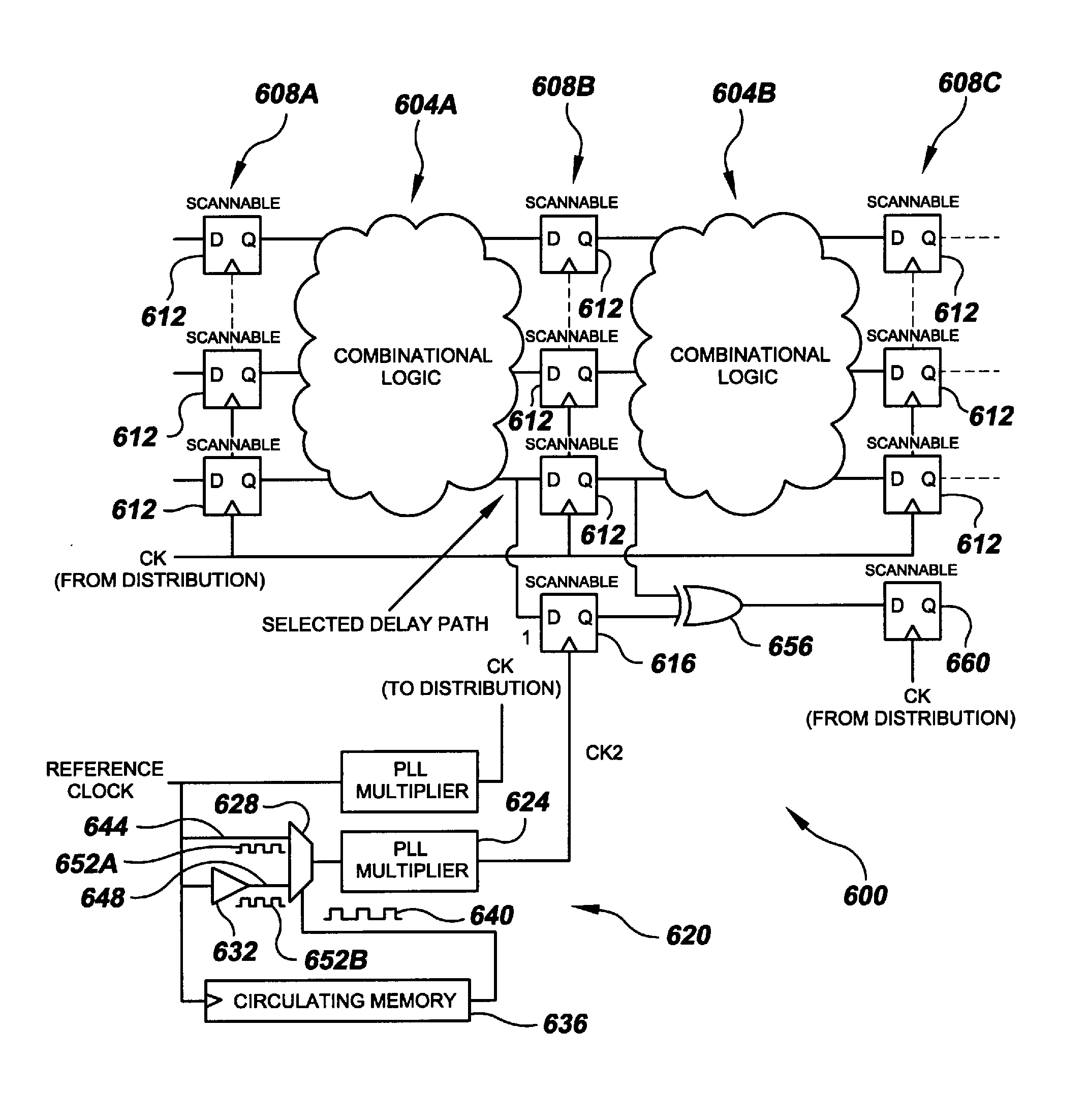
[0008]In yet another implementation, the present invention is directed to a method of implementing delay-fault testing for an integrated circuit. The method includes: during a design phase of designing an integrated circuit, identifying small delay paths from a plurality of data paths; providing ones of the plurality of data paths with a corresponding respective plurality of first scannable memory elements; providing the integrated circuit with additional, second scannable memory elements to the outputs of the small delay paths; providing the integrated circuit with further, third scannable memory elements in communication with corresponding respective ones of the second scannable memory elements, the third scannable memory elements for capturing delay-fault signals; providing the integrated circuit with a functional c

Problems solved by technology

Various new failure mechanisms plague modern nanometer-scale integrated circuits.
Reduced voltage swings, increased current consumption, the introduction of new materials, and unprecedented densities render such circuits increasingly sensitive to phenomena like local temperature variations within a chip, local power supply voltage variations, clock jitter, and small resistive / capacitive defects.
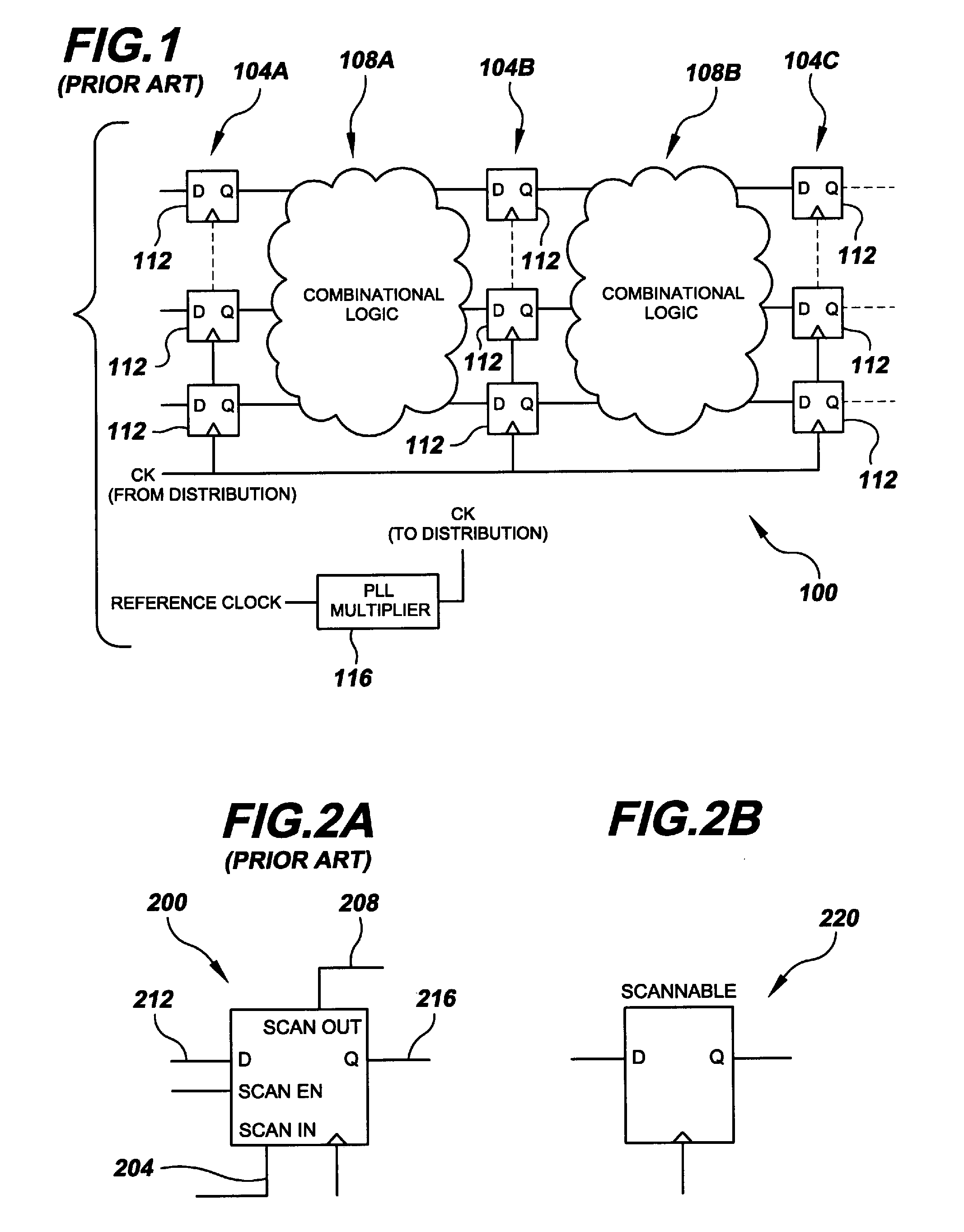
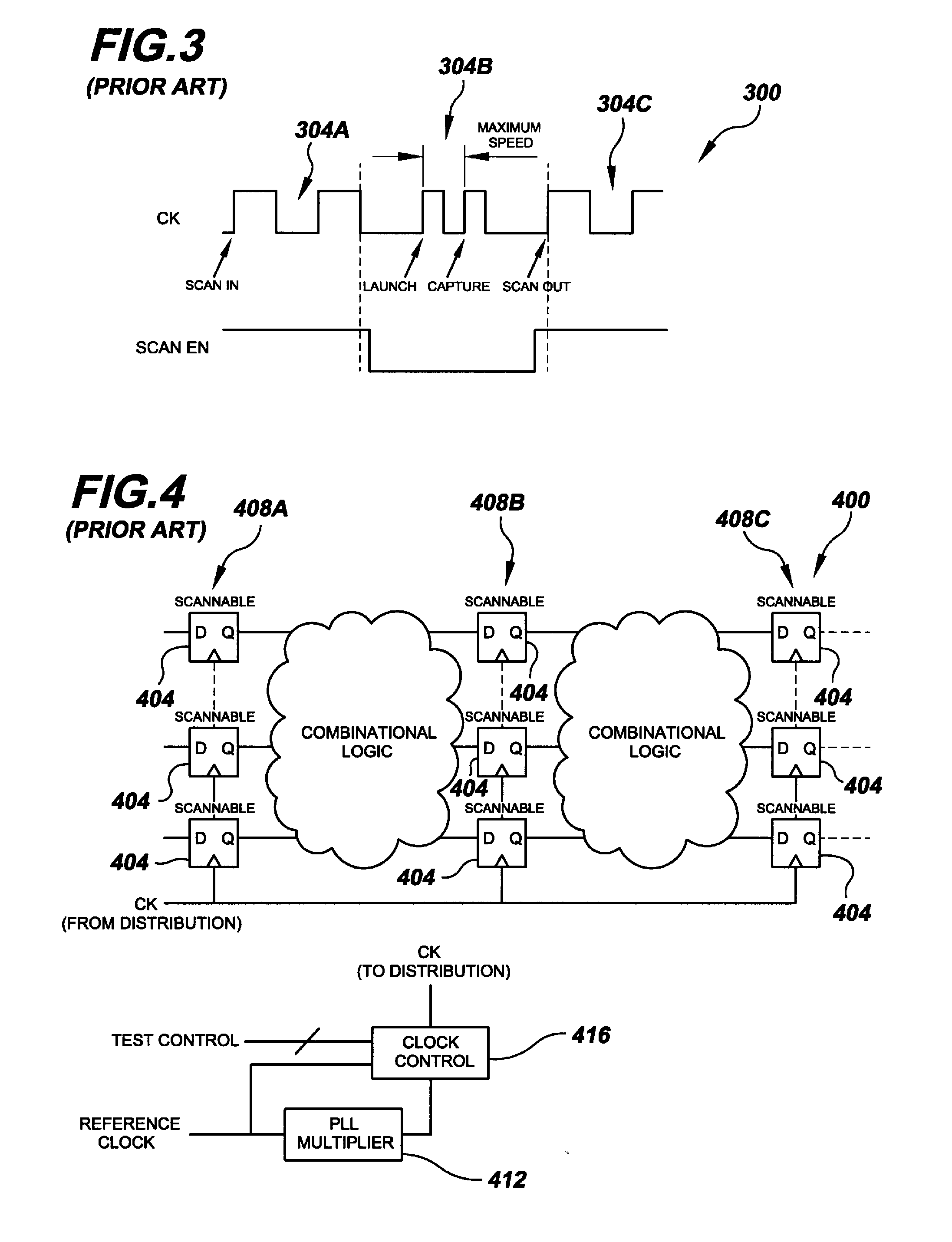
In the present state of the art, conventional test methods do not cover timing-related faults effectively.
Thus, the latter represent a significant risk of increased test escapes, which are defined as failing parts that are not caught before shipment, or increased reliability escapes, which are defined as functional parts that suffer from premature failure in the field.
When it comes to testing chips in large volume, ring-oscillator monitors become ineffective since they require calibration and offer too little resolution.
Small delay faults are notorious in that they pass conventional structural test methods without being detected.
Unfortunately, a failing over-speed vector does not necessarily mean the part being tested is really defective since the latter was not designed to operate at this fast clock frequency in the first place.

Method used


Image

  • Systems and Methods for Testing and Diagnosing Delay Faults and For Parametric Testing in Digital Circuits
  • Systems and Methods for Testing and Diagnosing Delay Faults and For Parametric Testing in Digital Circuits
  • Systems and Methods for Testing and Diagnosing Delay Faults and For Parametric Testing in Digital Circuits

Examples


Embodiment Construction

[0030]At a high level, the present invention relates to the test and mitigation of the issues described above in the Background section during two distinct phases: debug / diagnosis and production testing. These two phases have slightly different logistical requirements, but they are equally important for quality maintenance at any chip or digital system provider. The logistical differences relate to test time, amount of data collection, and test data availability. The electrical requirements, on the other hand, are similar. The goal of both is to screen subtle timing-related failures that are not screened using conventional structural test techniques.

[0031]Given the situation described in the Background section above, there is a dire need for new on-chip measurement solutions for both production testing and debug / diagnosis. This disclosure describes delay-fault test circuits and methods that significantly enhance coverage for both production testing as well as debug and diagnostics. ...


PUM


Abstract

Delay-fault testing and parametric analysis systems and methods utilizing one or more variable delay time-base generators. In embodiments of the delay-fault testing systems, short-delay logic paths are provided with additional scan-chain memory elements and logic that, in conjunction with the one or more variable-delay time-base generators, provides the effect of over-clocking without the need to over-clock. Related methods provide such effective over-clocking. In embodiments of parametric analysis systems, test point sampling elements and analysis circuitry are clocked as a function of the output of the one or more variable-delay time-base generators to provide various parametric analysis functionality. Related methods address this functionality.

Description

FIELD OF INVENTION[0001]The present invention relates generally to integrated circuits testing and diagnosis. More particularly, the present invention is directed to systems and methods for testing and diagnosing delay faults and for parametric testing in digital circuits.BACKGROUND[0002]Various new failure mechanisms plague modern nanometer-scale integrated circuits. Reduced voltage swings, increased current consumption, the introduction of new materials, and unprecedented densities render such circuits increasingly sensitive to phenomena like local temperature variations within a chip, local power supply voltage variations, clock jitter, and small resistive / capacitive defects. A common theme among these effects is that they are not uncovered using conventional debug and test methods. In other words, failures due to these effects do not manifest themselves in conventional ways; rather, they are timing related. Simplistically, they affect the maximum speed at which a circuit can ope...

Claims


Application Information

Patent Timeline
IPC IPC(8): G01R29/26G06F11/00G06F19/00
CPCG01R31/31858
Inventor HAFED, MOHAMED M.
Owner DFT MICROSYST
Learn More