
Proximity sensing systems for manufacturing quality control

a technology of proximity sensing and manufacturing quality control, which is applied in the direction of program control, instruments, computing, etc., can solve the problems of affecting the manufacturability of materials, affecting the quality of materials, and difficult to maintain the alignment of machine tools, so as to increase manufacturing reliability and product throughput, and expand the scope of quality control

Inactive Publication Date: 2009-08-06
NORTHROP GRUMAN CORP
View PDF4 Cites 32 Cited by
  • Summary
  • Abstract
  • Description
  • Claims
  • Application Information

AI Technical Summary

Benefits of technology

[0013]Thus, the machinist can remotely monitor the positioning of the workpieces to the trim fixture vacuum, increasing manufacturing reliability and product throughput. Multiple proximity sensors may be monitored simultaneously to expand quality control coverage. The present invention will be best understood by reference to the following detailed description when read in conjunction with the accompanying drawings.

Problems solved by technology

However, composite materials are often difficult to properly machine because of expansion and movement associated with spring back—a reaction of the material to reduce the stress induced by shaping, and temperature and pressure changes.
These dynamic characteristics adversely affect the manufacturability of the material, in that proper alignment to machine tools is difficult to maintain.
One difficulty with sole reliance upon the tool fixture vacuum, however, is that it is uncertain whether all areas of the composite part are properly distanced from the tool surface within the area inside the seal barrier prior to machining.
Because this area is obscured and inaccessible, there is difficulty in determining proper contact of the part with respect to the machine tool.
If a part is not braced in such hidden areas, material may be removed excessively, resulting in a non-conformance.
Without verifying the proximity of the material to the machine tool, there is a higher likelihood of it being machined outside the acceptable tolerance.
This is particularly problematic in the manufacture of high-quality, tight tolerance parts such as those used in aircraft, where seemingly insignificant discrepancies are anything but.
As a consequence, the supply chain is disrupted, production time is increased, and availability is reduced.
Furthermore, manufacturing costs are increased because of the added labor and raw material costs.
Generally, the quality of the final product is diminished when its constituent parts cannot be accurately and repeatedly produced.
This technique is limited, however, in that there is substantial variance from one machinist to the next due to the flexible verification procedures.
Furthermore, feeler gauges are limited to those areas that can be accessed, and are also limited by the length constraints of the gauge.
Due to the manual nature of this technique, it is difficult to maintain an efficient workflow during manufacturing operations, considering that prior to beginning each machining step, the spacing has to be verified.
All of these factors combine to increase the probability that the composite part is out-of-tolerance in relation to the machine tool.

Method used


Image

  • Proximity sensing systems for manufacturing quality control
  • Proximity sensing systems for manufacturing quality control
  • Proximity sensing systems for manufacturing quality control

Examples


Embodiment Construction

[0024]The detailed description set forth below in connection with the appended drawings is intended as a description of the presently preferred embodiment of the invention, and is not intended to represent the only form in which the present invention may be constructed or utilized. The description sets forth the functions of the invention in connection with the illustrated embodiment. It is to be understood, however, that the same or equivalent functions and may be accomplished by different embodiments that are also intended to be encompassed within the scope of the invention. It is further understood that the use of relational terms such as first and second and the like are used solely to distinguish one from another entity without necessarily requiring or implying any actual such relationship or order between such entities.

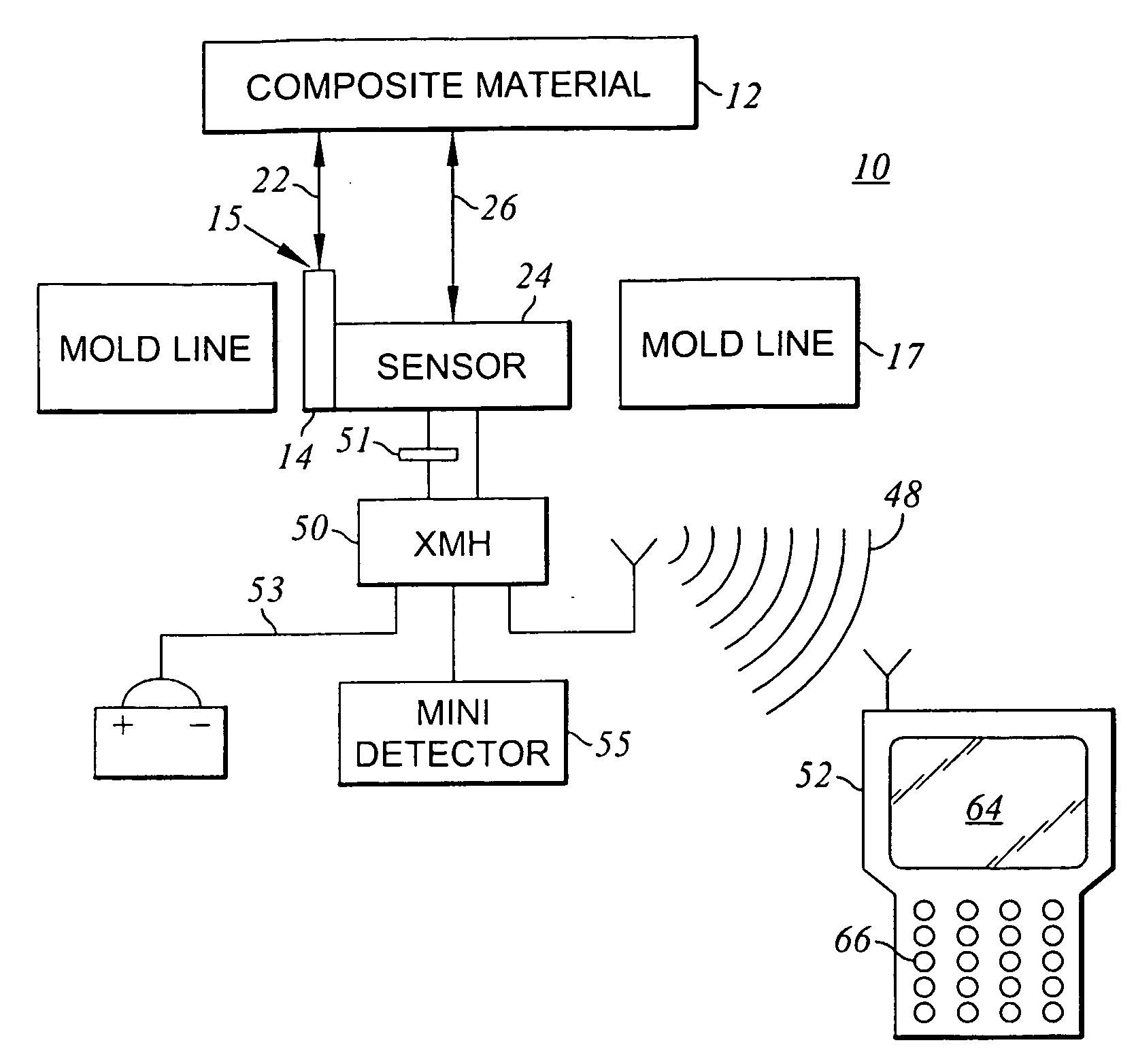
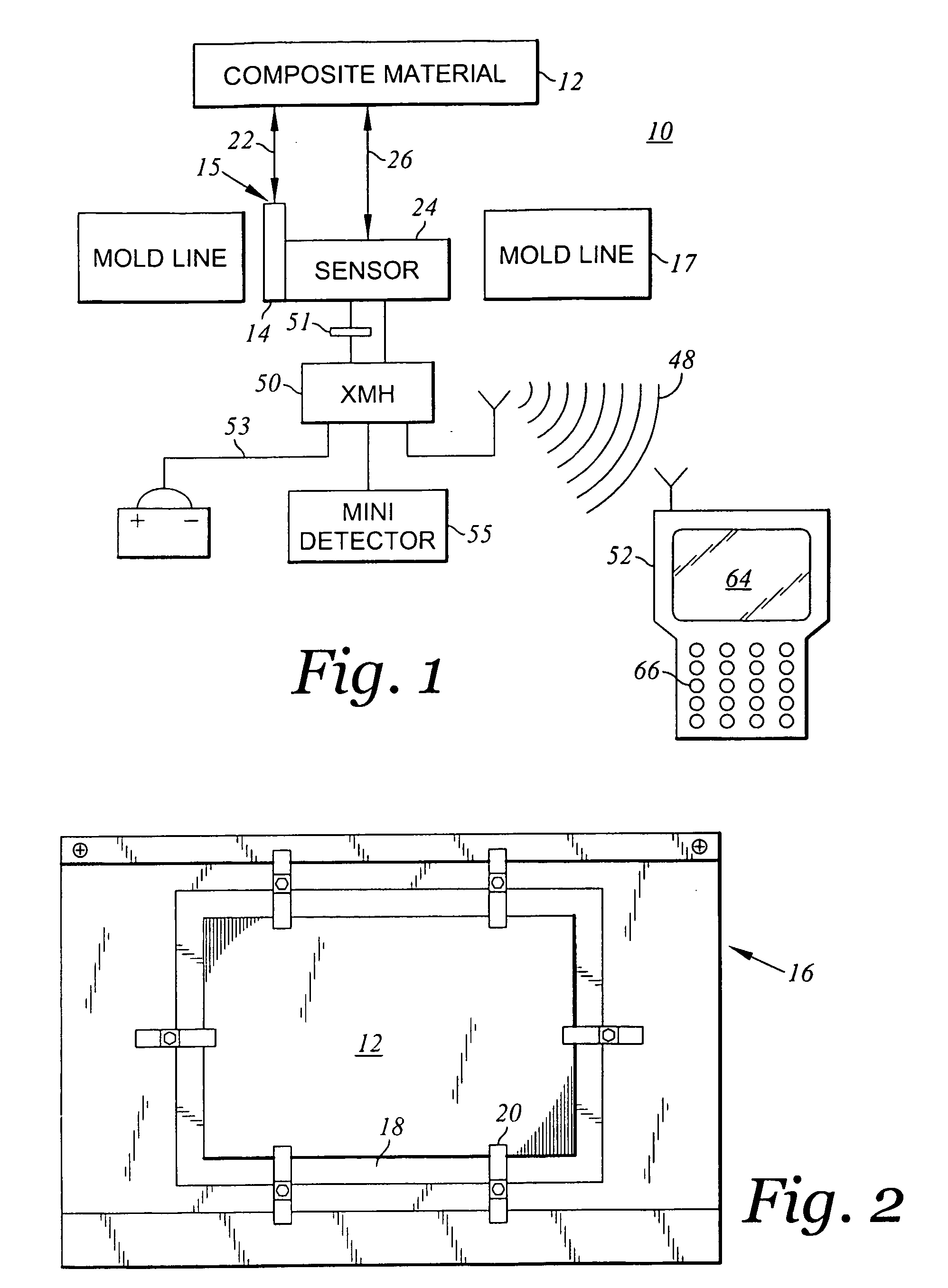
[0025]With reference to FIG. 1, according to one embodiment of the present invention, a manufacturing quality control system 10 monitors the proximity of a work...


PUM


Abstract

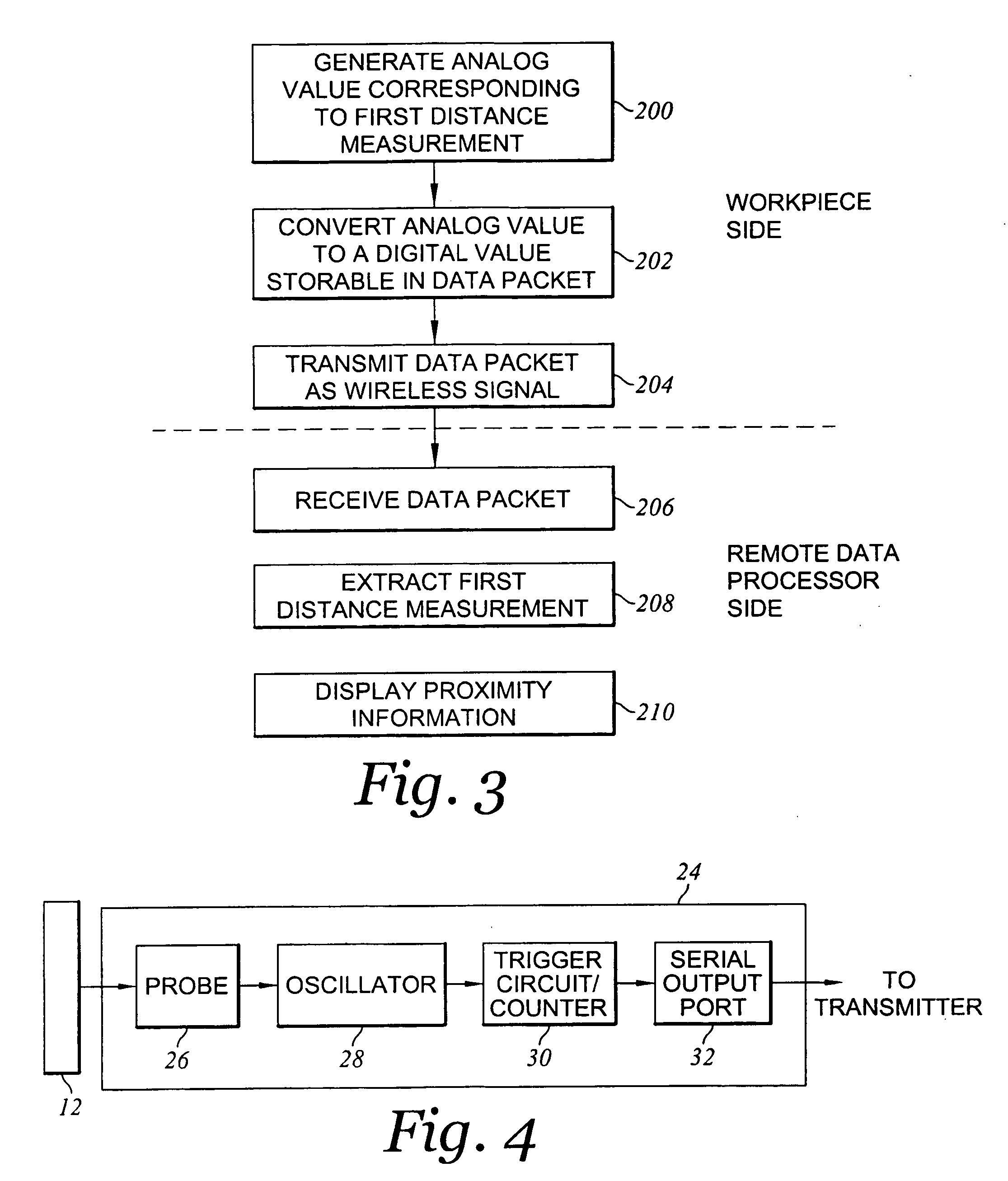
A manufacturing quality control system for monitoring the proximity of a workpiece to a machine tool is disclosed. The system includes a proximity sensor attached to the machine tool for deriving a first distance measurement based upon the distance between the workpiece and the machine tool. A wireless transmitter generates a radio frequency signal including the first distance measurement. A remote data processing device communicates with the wireless transmitter to retrieve the first distance measurement and display various derivations of sensor data.

Description

CROSS-REFERENCE TO RELATED APPLICATIONS[0001]Not ApplicableSTATEMENT RE: FEDERALLY SPONSORED RESEARCH / DEVELOPMENT[0002]Not ApplicableBACKGROUND[0003]1. Technical Field[0004]The present invention generally relates to quality control systems and methods in manufacturing operations. More particularly, the present invention relates to proximity sensing of work pieces from machine tools to maintain close manufacturing tolerances. Further, the present invention relates to proximity sensing systems that can communicate wirelessly or wired with remote data processing devices.[0005]2. Related Art[0006]Composites, which are materials comprised of two or more constituent materials having divergent properties, are frequently utilized in the manufacture of aircraft and other heavy machinery for its light weight, high strength, and extended fatigue life. However, composite materials are often difficult to properly machine because of expansion and movement associated with spring back—a reaction of...

Claims


Application Information

Patent Timeline
IPC IPC(8): G06F19/00
CPCG05B19/402G05B2219/37397G05B2219/37277
Inventor DECKER, DOUG DEANSHINBARA, TIMOTHY JACKSONWARDELL, JOSEPH PAUL
Owner NORTHROP GRUMAN CORP
Learn More