

Organic solar cell
a solar cell and organic technology, applied in the field of organic solar cells, can solve the problems of reducing the efficiency of light use, reducing the selection of materials, and increasing the energy consumption of the whole structure,
Inactive Publication Date: 2009-08-13
PIONEER CORP +2
View PDF3 Cites 35 Cited by
- Summary
- Abstract
- Description
- Claims
- Application Information
AI Technical Summary
Benefits of technology
The present invention provides an organic solar cell that can efficiently receive and use light from the opposite side of the substrate. By using an alloy containing magnesium in the second electrode, the thickness of the electrode can be reduced, and the efficiency of using incident light is increased. Additionally, the use of a transparent substrate and electrodes is not limited, and the use of a thicker electrode does not affect the efficiency of using incident light. The invention also addresses the problem of damaging the organic solid layer when using a thick transparent electrode. The technical effects of the invention include increased efficiency of using incident light and reduced damage to the organic solid layer.
Problems solved by technology
In recent years, energy consumption drastically increases along with industrial development.
However, since it is necessary to select a trans parent material as the substrate and the anode, there is a problem that there is a limited option in selecting the material.
However, there occur a problem that a part of incident light is locked inside the transparent electrode and further the transparent substrate when such the relatively thick transparent electrode is used, thereby lowering efficiency of using the light, as disclosed in Patent Document 1.
Method used
View moreImage
Smart ImageViewing Examples

Examples
example 2
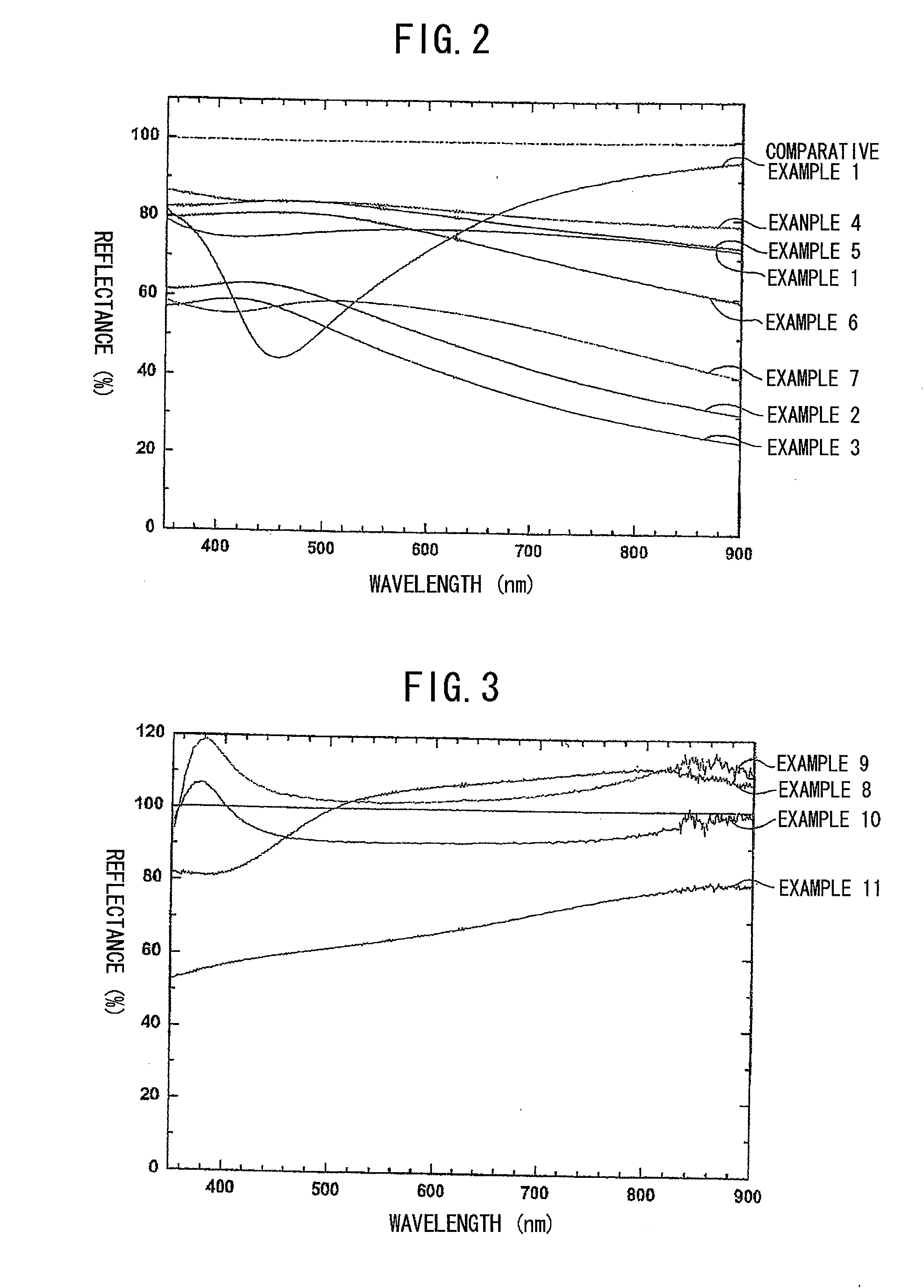
[0062]There was manufactured a cathode of Example 2, i.e. an alloy containing magnesium (a thickness of 7.5 nm) having a ratio of magnesium (Mg) and silver (Ag) being 1:10.
example 3
[0063]There was manufactured a cathode of Example 3, i.e. an alloy containing magnesium (a thickness of 10.0 nm) having a ratio of magnesium (Mg) and silver (Ag) being 1:10.
example 4
[0064]There was manufactured a cathode of Example 4 (a total thickness of layer being 2.5 nm) formed by silver (Ag) (a thickness of 0.5 nm) and an alloy containing magnesium (a thickness of 2.0 nm) having a ratio of magnesium (Mg) and silver (Ag) being 1:10.
Login to View More PUM
| Property | Measurement | Unit |
|---|---|---|
| thickness | aaaaa | aaaaa |
| total thickness | aaaaa | aaaaa |
| thickness | aaaaa | aaaaa |
Abstract
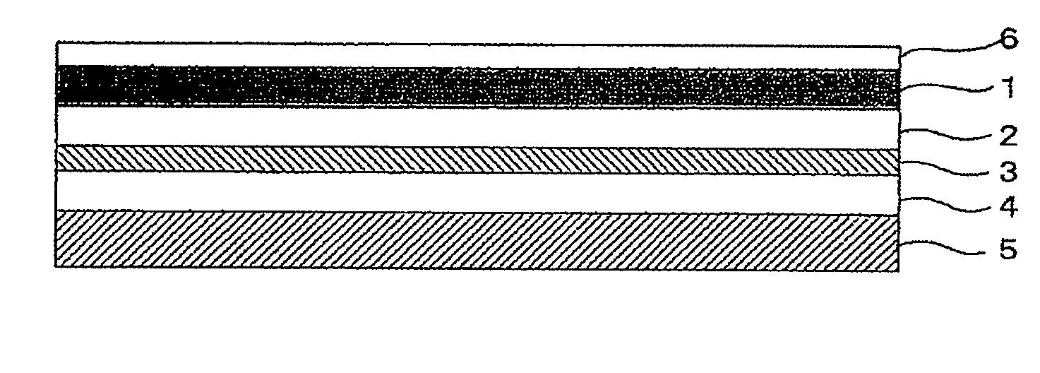
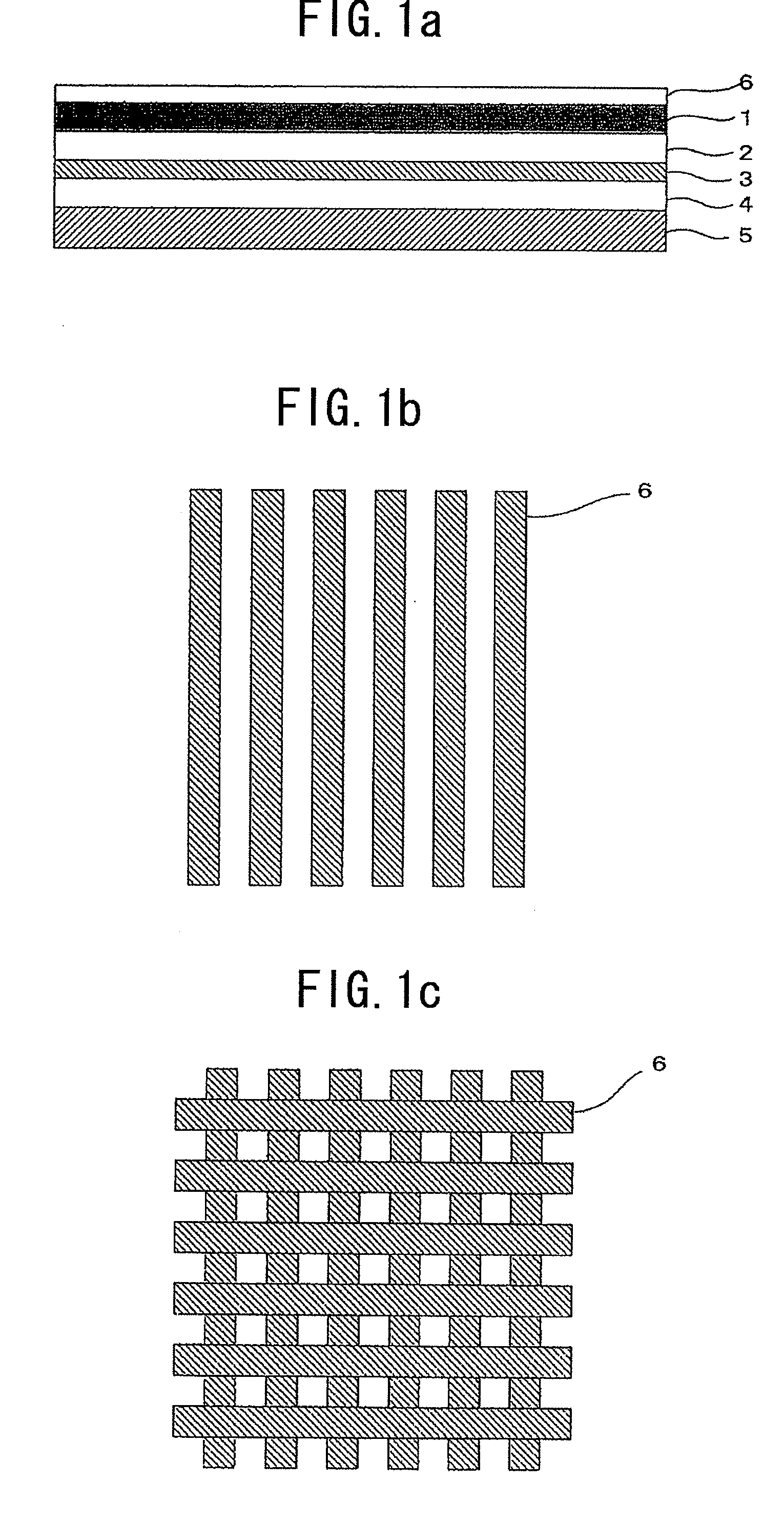
To provide an organic solar cell in which a light is preferably introduced from a side opposite to a substrate and the light thus introduced can be efficiently used.The organic solar cell including a substrate; a first electrode; an organic solid layer; and a second electrode, laminated in this order, wherein the second electrode is made from an alloy containing magnesium and has a thickness of 1 to 20 nm.
Description
TECHNICAL FIELD[0001]The present invention relates to a technical field of an organic solar cell formed by laminating a substrate, a first electrode, a second electrode.BACKGROUND ART[0002]In recent years, energy consumption drastically increases along with industrial development. Under such the situation, it is required to develop a new and clean energy source having an economical efficiency and a high performance and without causing burden to the global environment. A solar cell is paid attention to out of those prospected as the new energy source since it utilizes inexhaustible sunlight. The solar cell is structured to laminate a substrate, a first electrode (anode), an organic solid layer, and a second electrode (cathode). In the solar cell thus structured, it is ordinary to make light incident on a side of the substrate. For this, it is necessary to use a transparent substrate and a transparent electrode respectively for the substrate and the anode. Specifically, there has been...
Claims
Login to View More Application Information
Patent Timeline
 Patent Type & AuthorityApplications(United States)
IPC IPC(8): H01L31/0256
CPCB82Y10/00H01L51/0046Y02E10/549H01L51/424H01L51/442H01L51/422H10K85/211H10K30/20H10K30/82H10K30/50H10K30/15
InventorOYAMADA, TAKAHITOADACHI, CHIHAYA
OwnerPIONEER CORP