
Cover, a container assembly including the cover, a molding device for molding the cover and a method for manufacturing the cover

a container assembly and cover technology, applied in the field of containers and covers, can solve the problems of high production cost, insufficient reduction of manufacturing cost, and blowing out the cover or destroying the container

Active Publication Date: 2009-08-13
IWASAKI IND
View PDF3 Cites 32 Cited by
  • Summary
  • Abstract
  • Description
  • Claims
  • Application Information

AI Technical Summary

Benefits of technology

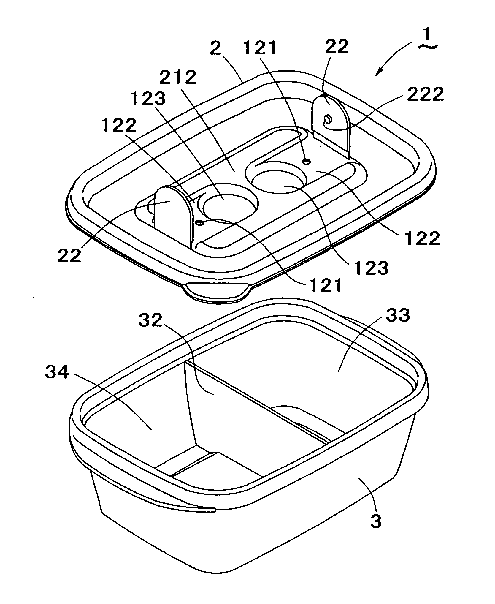
[0043]A cover of the present invention is configured to exhaust a water vapor from a food stuff or an inflating air in a container assembly through at least one aperture by upwardly rotating a flap (e.g. when heating the food stuff inside the container assembly). Therefore, the cover does not have to be removed from the container when heating. Further, the food stuff in the container assembly may be hygienically stored (for example, in a refrigerator) by engaging a protrusion of the flap with the aperture of the cover body after rotating the flap downwardly.
[0044]The cover body and the at least one flap are formed by a co-injection molding without requiring any complicated additional process such as a double-molding process or an assembly process. Further, the flap does not drop off the cover. An attempt to mold the cover including the at least one flap by the co-injection molding has not been made due to the complicated shape of the cover. However, thanks to many researches for a resin-molding mold by the present inventors, the flap and the cover can be molded by the co-injection molding, i.e. by injecting a molten resin into a cavity defining the cover body and a flap standing uprightly with respect to the cover body.
[0050]When the flap rotates upwardly until it stands uprightly to the cover body, a groove with an arc cross section appears in a lower surface of the flap at the proximal end. On the other hand, a flat upper surface of the flap appears behind the groove. This configuration limits an upward rotation of the flap from a parallel to an upright position with respect to the upper surface of the cover body. Thus, an excess repeated bending stress on the proximal end of the flap can be avoided so that a life (usable period) of the cover may be extended.
[0054]Thus, cover and the container assembly molded from the above-described resin may have a heat resistance comparable to a resin film used for a microwave cooking. A dish dryer may be applicable to the cover and the container because they are dishwasher-safe. Further, the high crystallinity polypropylene resin may increase an acceptable rotational repetition (a number of repetition of the flap rotation until the proximal end of the flap breaks).
[0057]The present invention further provides a molding device and a manufacturing method for manufacturing a cover and a container assembly including the cover having the above-described advantages.

Problems solved by technology

This is because an increase in an inner pressure of the container assembly during heating process due to an airtight sealing by the cover attached to the container may blow out the cover or destroy the container.
The container assembly disclosed in Japanese Patent No. 3513599 has a disadvantage of high production cost although it has a superior feature to overcome the conventional inconvenience when in use, because the cover (L) is manufactured through the double-molding process which requires many process steps.
However, the assembly process is still required, therefore reduction in the manufacturing cost may not be enough.
Further, the container assembly (C) in FIG. 16 has another problem.
A reattachable configuration of the flap (F) may somehow overcome the above-described problem, but if the flap (F) is lost after dropping off, the container assembly is no longer reparable.

Method used


Image

  • Cover, a container assembly including the cover, a molding device for molding the cover and a method for manufacturing the cover
  • Cover, a container assembly including the cover, a molding device for molding the cover and a method for manufacturing the cover
  • Cover, a container assembly including the cover, a molding device for molding the cover and a method for manufacturing the cover

Examples


Embodiment Construction

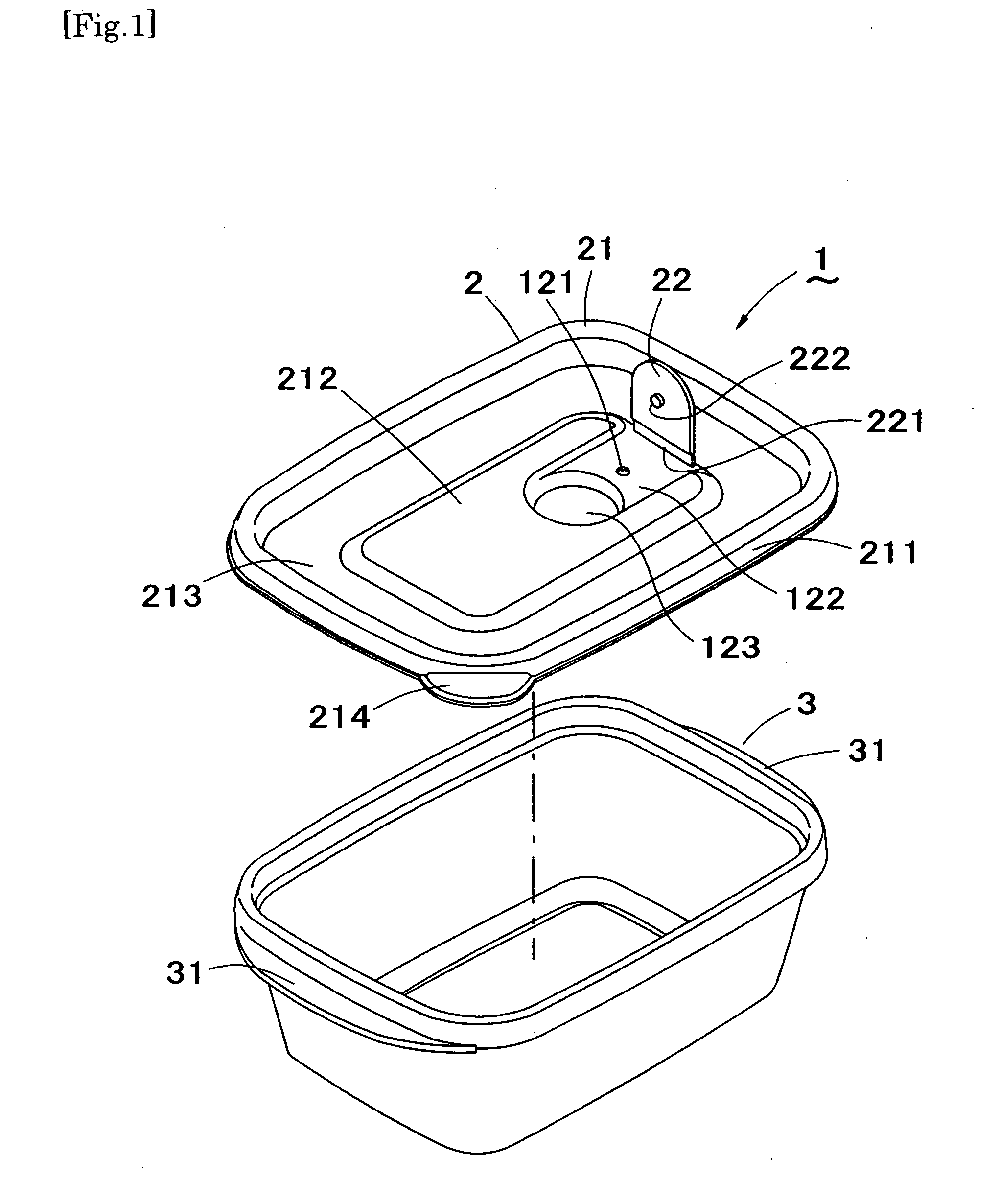
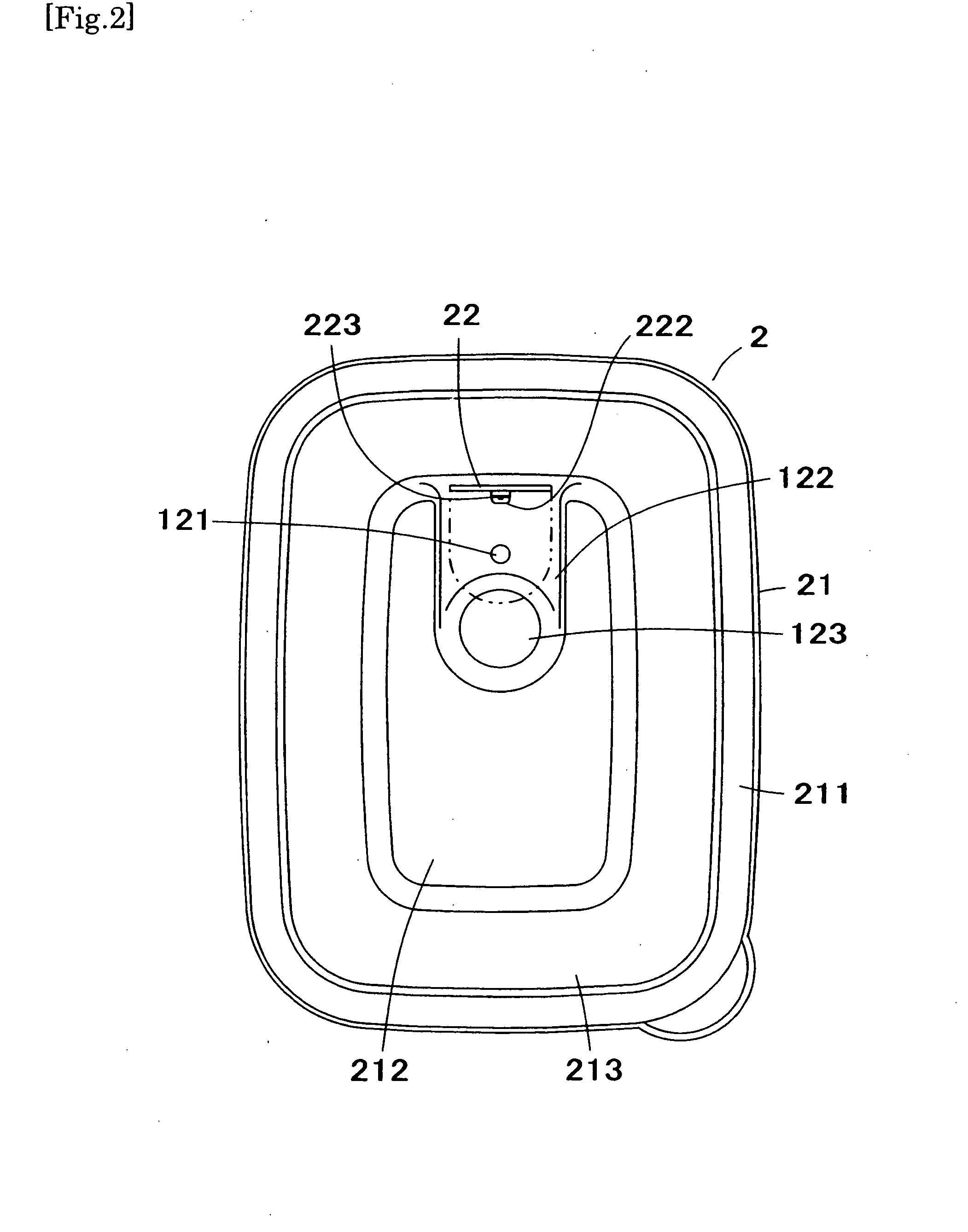
[0075]FIG. 1 is an exploded perspective view of the container assembly of the present invention. FIG. 2 is a plain view of the cover of the present invention.

[0076]A container assembly (1) comprises a cover (2) and a container (3). The container (3) has a substantially rectangular cylindrical shape shown in FIG. 1 but not limited to this. It may also have a cylindrical / oval cylindrical shape comprising a bottom, or a triangular cylinder or other polygonal shape. The container (3) contains a desired food stuff. A couple of ears (31) extending from peripheral edges of the container (3) in parallel to each other are configured to facilitate carriage / handling of the container assembly (1).

[0077]The cover (2) is configured to have a shape and a size for covering a top opening of the container (3), and an example in FIG. 1 and FIG. 2 shows a substantially rectangular cover (2) similar to a contour of the container (3).

[0078]A cover (2) includes a cover body (21) and a flap (22). The cover...


PUM

PropertyMeasurementUnit
rotationaaaaaaaaaa
rotationaaaaaaaaaa
heat resistanceaaaaaaaaaa

Abstract

[Purpose]To provide a container assembly suitable for heating a food stuff therein with a heating device such as a microwave and a cover thereof.[Solution]A cover for covering an opening of a container for a food stuff comprising: a substantially flat cover body including at least one aperture, at least one substantially flat flap including a linear proximal end configured to connect with the cover body, the proximal end allowing the at least one flap to rotate with respect to the cover body, wherein a lower surface of the at least one flap includes a protrusion configured to close the at least one aperture when the at least one flap is at a first position in which the at least one flap is in parallel with the cover body, the cover body and the at least one flap are integrally formed by a co-injection molding.

Description

CROSS REFERENCE TO RELATED APPLICATIONS[0001]This application is a continuation, as authorized by 35 U.S.C. §365(c), of International Application No. PCT / JP2007 / 069867, filed on Oct. 11, 2007, which claims priority of Japanese Patent Application No. 2006-280237, filed on Oct. 13, 2006, the entire content and disclosure of the preceding applications are incorporated by reference into this application.BACKGROUND OF THE INVENTION[0002]1. Field of the Invention[0003]This invention relates to a container assembly for a food stuff and a cover thereof. Further, this invention relates to the container assembly and the cover suitable for cooking a food stuff therein with a heating device such as a microwave.[0004]2. Description of the Related Art[0005]A container assembly comprising a container for a food stuff and a cover for covering an opening on a top of the container is often used in a daily life, for example, as a container assembly may contain a food stuff and then may be placed in a ...

Claims


Application Information

Patent Timeline
Patent Type & Authority Applications(United States)
IPC IPC(8): H05B6/80B65D51/16B65D51/18B65D81/34
CPCB29C45/0081B29C45/33B29C45/4421B65D41/16B65D43/0214B29L2031/565B65D51/1683B65D81/34B65D51/16B65D51/24B65D77/20B29C45/0017B29K2023/12B29K2995/0041B65D43/0204B65D81/3453
Inventor IWASAKI, YOSHIHISA
Owner IWASAKI IND
Learn More