
Conductive composite material

a composite material and conductive technology, applied in the field of composite materials, can solve the problems of high cost, broken conduction path, multi-stage process, time-consuming and costly heating steps, etc., and achieve the effect of high transparency

Inactive Publication Date: 2009-08-13
EASTMAN KODAK CO
View PDF4 Cites 1 Cited by
  • Summary
  • Abstract
  • Description
  • Claims
  • Application Information

AI Technical Summary

Benefits of technology

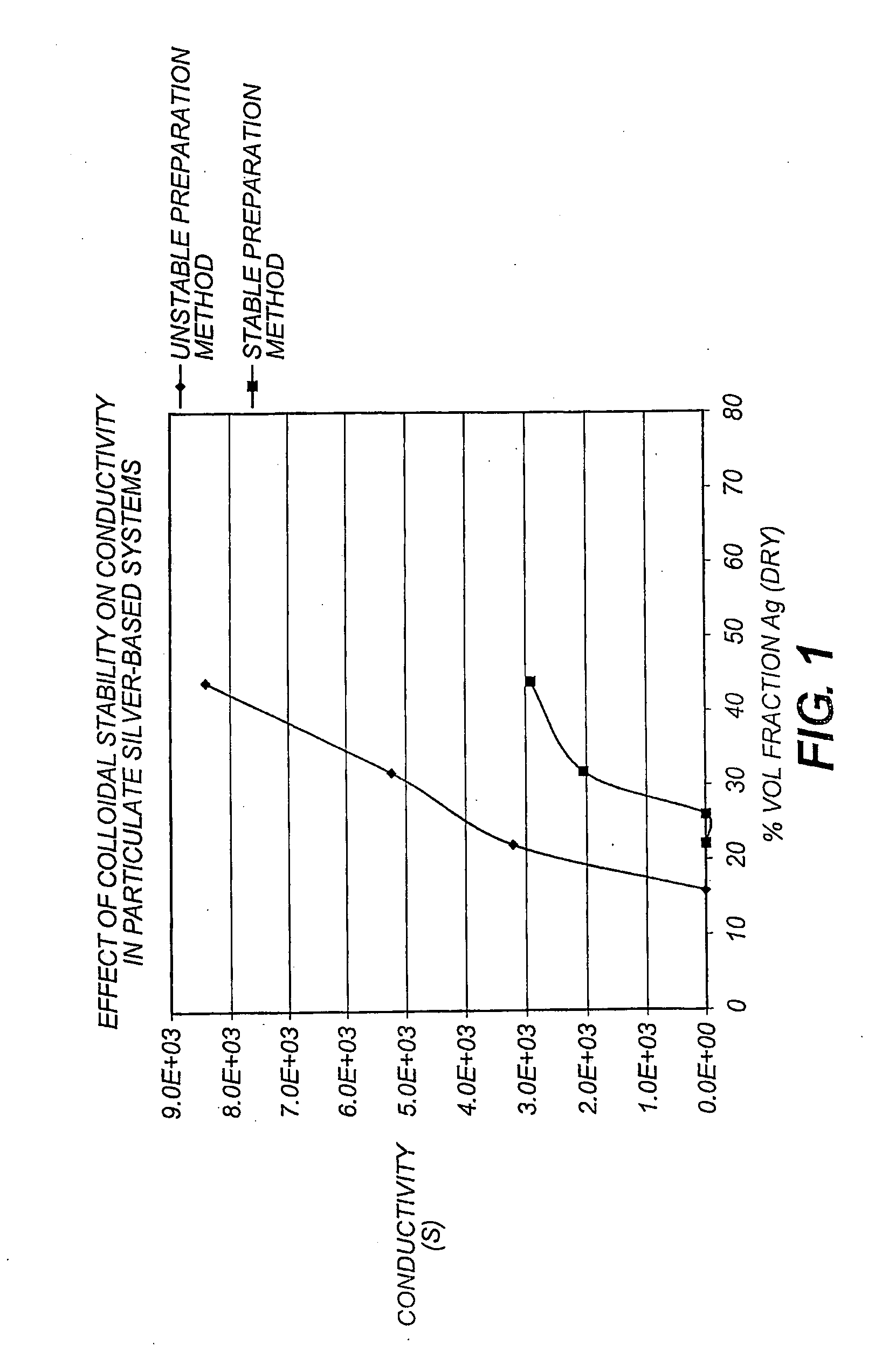
[0012]As the “connected wires” which make up the network consist of interconnected particles with thicknesses comparable to the particle diameter they can be made very thin. This gives rise to high transparency which is advantageous for the production of transparent conductors for display type devices.
[0013]Less conductive material is needed to give the same conductivity as those composites formed by a collidably stable system.

Problems solved by technology

However, the process is an expensive one.
In addition, ITO coatings such as these however, tend to suffer from brittleness, so that when flexed, the ITO cracks creating breaks in the conduction path.
However, this is a fairly complicated, multi-stage process that includes a time consuming and costly heating step.
There is also the problem of ensuring a good electrical connection, since the transparent top layer is essentially an insulator.
However, if the dimensions of these aggregates lie outside the ranges given, it is very much more difficult to form a connected network structure, and as a consequence there is a detrimental effect on the surface resistivity.
Such a process involves a large number of different steps which makes it time consuming and relatively costly.
In the industry, the requirements of the ink needed to produce significant conductivity in a single pass are not well defined or well understood.

Method used


Image

  • Conductive composite material
  • Conductive composite material

Examples


example 2

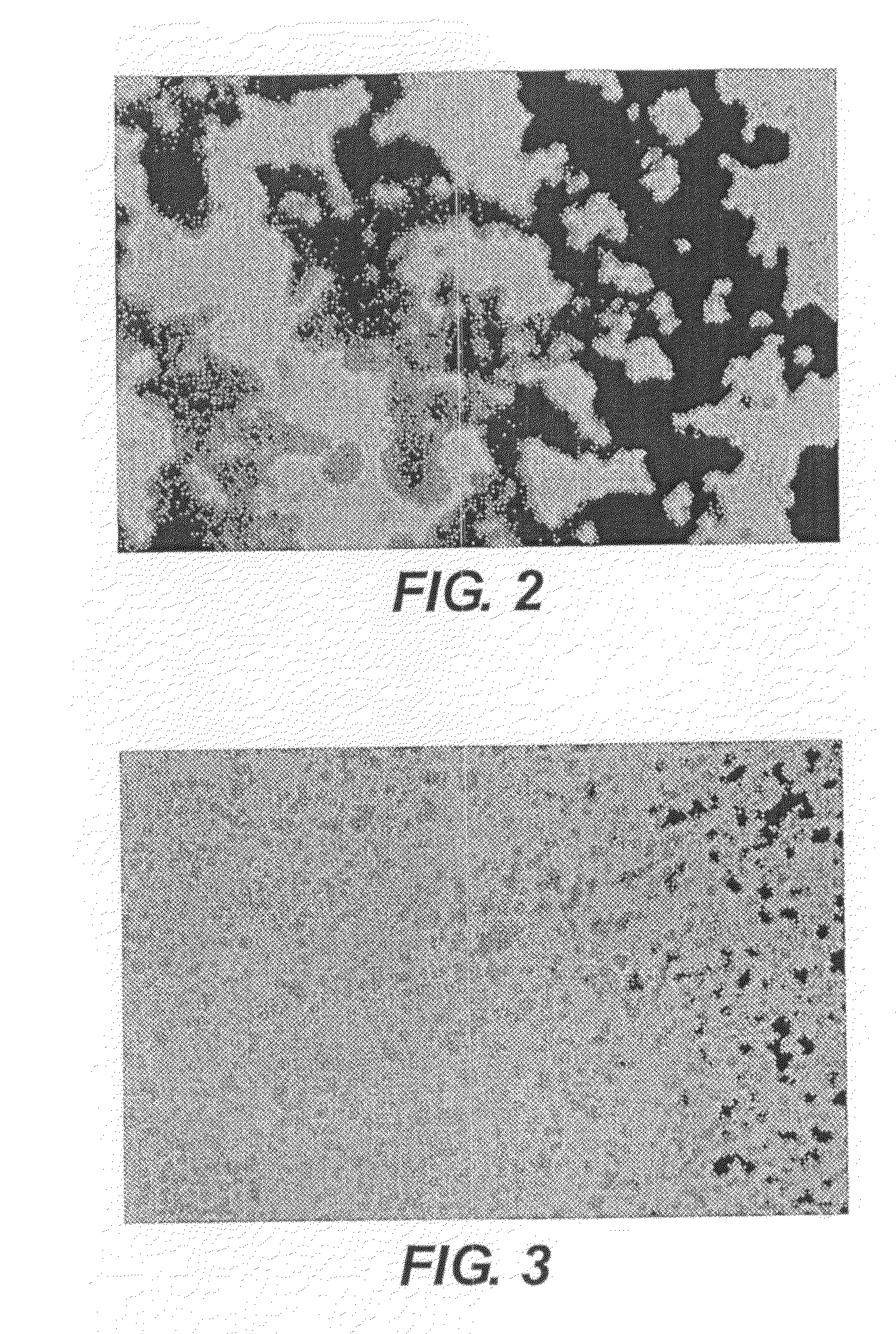
[0027]A solution with 7.8% w / w silver flakes, 0.16% w / w Surfynol CT131 and 2.4% w / w Type IV gelatin was prepared. The gelatin was soaked in the required water and was gradually melted with regular stirring in a water bath at 45° C. The silver flakes were added to the solution and the mixture was vigorously stirred for around 15 minutes on a magnetic stirrer and then placed in an ultrasonic bath for around 15 minutes. Surfynol CT131 was added and the mixture was again stirred for around 15 minutes on the magnetic stirrer and then placed in the ultra sonic bath for 15 minutes. Finally, the Alkanol XC was added at 0.02% w / w and the melt stirred thoroughly. The mixture was hand coated at a wet thickness of 50 μm to give a final dry layer with 26% v / v silver and a thickness of 5.3 μm. The coatings were allowed to dry in air at room temperature and were then investigated using the optical microscope (see FIG. 3). In this case, discrete, colloidally stable silver particles are present in t...


PUM

PropertyMeasurementUnit
Flexibilityaaaaaaaaaa
Electrical conductoraaaaaaaaaa
Metallic bondaaaaaaaaaa

Abstract

A composite comprises conductive particles within a binder matrix, the particles being colloidably unstable within a solution and forming a conductive open network within the binder matrix when dried.

Description

FIELD OF THE INVENTION[0001]The present application relates to the field of composite materials having conducting particles within a binder matrix. When the particles are arranged in an open, connected network structure a conducting material is created. Low-cost, conductive composites can have application in any area where electrical conductivity is required in films, coatings, paints or inks. One application is in the manufacture of cheap, flexible conductors and electronics for use in areas such as RFID tags and large area displays.BACKGROUND OF THE INVENTION[0002]The present application relates to conductive composite materials that consist of conducting particles in a binder matrix. Conductivity is achieved in such systems when a connected conductive pathway is created within the matrix i.e. the percolation threshold is reached. Percolation is a statistical concept that describes the formation of an infinite cluster of connected particles or pathways. The percolation threshold m...

Claims


Application Information

Patent Timeline
IPC IPC(8): H01B1/02H01B1/22
CPCH01B1/22H05K2201/0245H05K1/095
Inventor BOWER, CHRISTOPHER L.SIMISTER, ELIZABETH A.PIGHTLING, NICHOLAS A.STEPHENSON, III, STANLEY W.
Owner EASTMAN KODAK CO
Learn More