Motor drive circuit

a motor drive and circuit technology, applied in the direction of mechanical power/torque control, single-phase motor control, emergency protective arrangements for limiting excess voltage/current, etc., can solve the problem of erroneous detection of overcurrent state, failure of an object to be protected from overcurrent, and temporary prohibition of overcurrent protection control

Active Publication Date: 2009-08-13
SEMICON COMPONENTS IND LLC
View PDF8 Cites 13 Cited by
  • Summary
  • Abstract
  • Description
  • Claims
  • Application Information

AI Technical Summary

Benefits of technology

[0023]A motor drive circuit according to an aspect of the present invention, comprises: a current passage control circuit configured to perform ON / OFF control of a drive transistor connected to a motor coil to pass current through the motor coil; an overcurrent state detection circuit configured to detect whether or not current passing through the drive transistor is in an overcurrent state where the current exceeds a predetermined threshold value; a charging and discharging circuit configured to start charging a capacitor in response to detecting the overcurrent state by the overcurrent state detection circuit and subsequently discharge the capacitor in response to not detecting the overcurrent state; and an overcurrent protection control circuit configured to stop the ON / OFF control of the drive transistor performed by the current passage control circuit to turn off the drive transistor, for an elapsed charging period for a charging voltage of the capacitor at a predetermined voltage to exceed a threshold voltage, and determine whether or not to perform such an overcurrent protection control as to turn off the drive transistor by detection of the overcurrent state, after the charging period has elapsed.

Problems solved by technology

However, there is a risk that the overcurrent state may be erroneously detected due to unexpected noise (a spike noise, etc.) superimposed on the drive current.
However, when having such a configuration, the overcurrent protection control is temporarily prohibited during the mask period, even though the overcurrent state is detected which is caused not by noise but by the accidental short circuit.
Therefore, when the mask period is set improperly long, there is a risk of a failure of an object to be protected from overcurrent (a motor coil, a drive transistor, etc.)
Therefore, it is difficult to appropriately set the length of the mask period as the charging period of the capacitor to reduce erroneous detections of the overcurrent state caused by noise.

Method used


Image

  • Motor drive circuit
  • Motor drive circuit
  • Motor drive circuit

Examples


Embodiment Construction

[0032]At least the following details will become apparent from descriptions of this specification and of the accompanying drawings.

>>

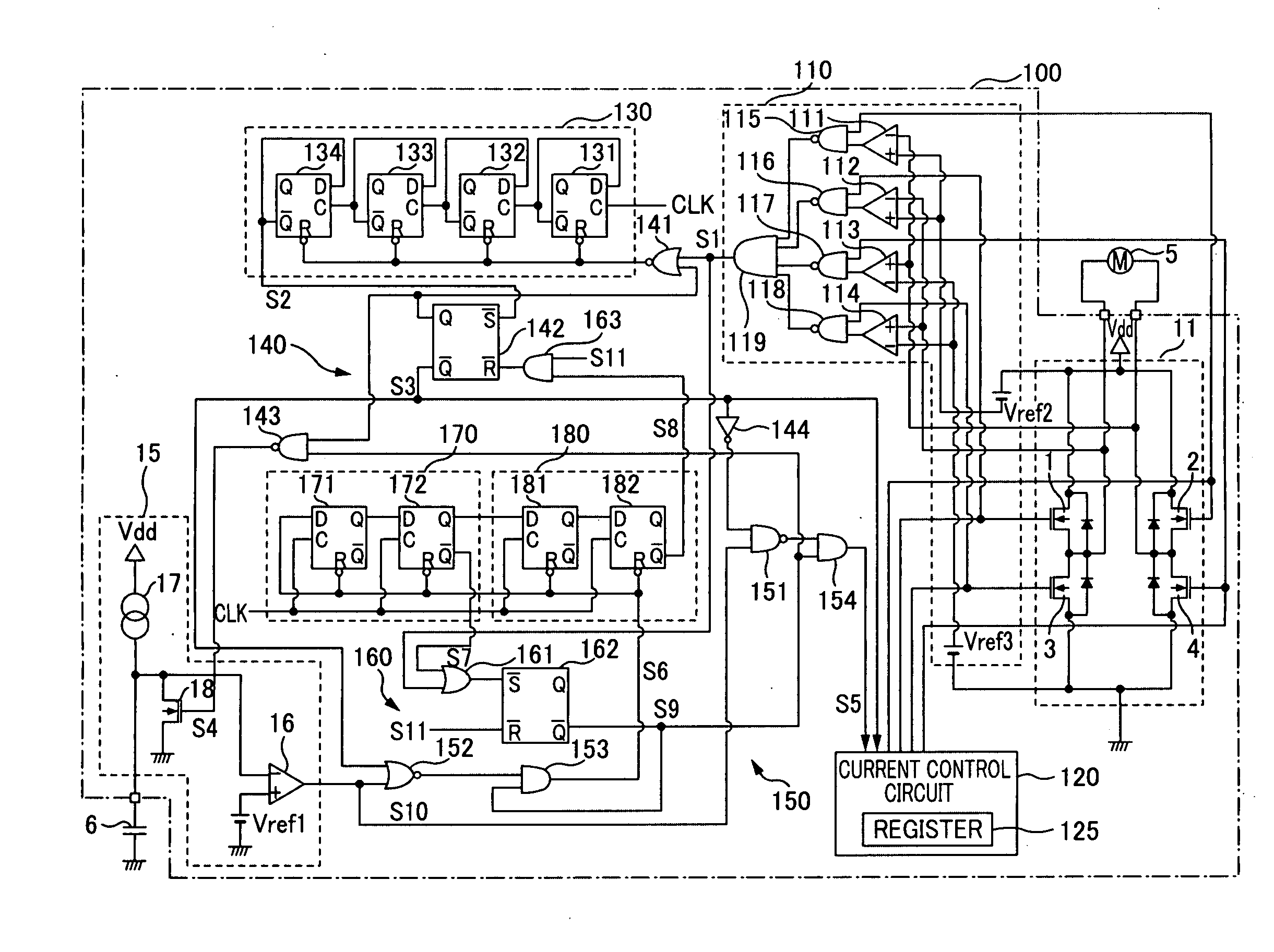
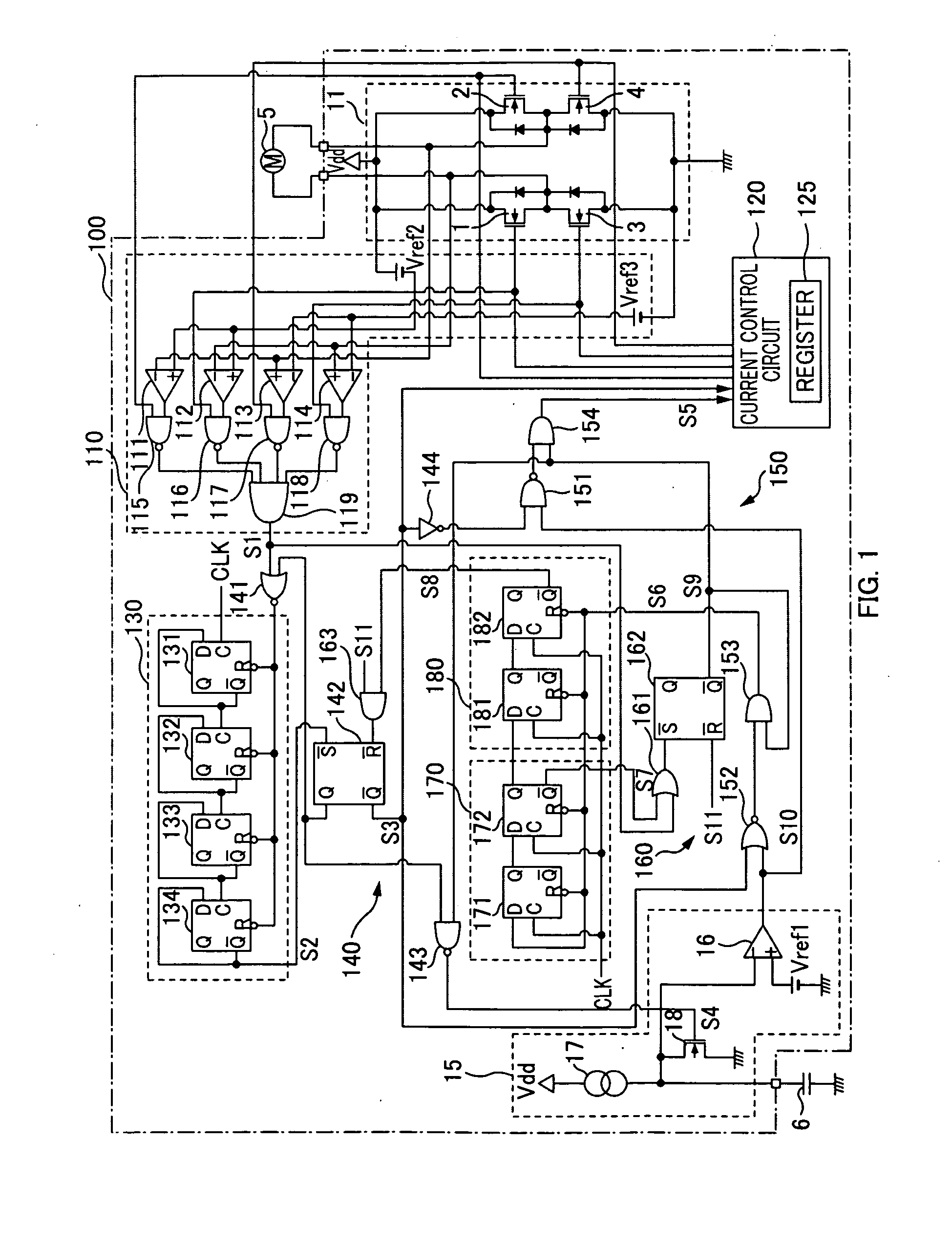
[0033]FIG. 1 is a block diagram illustrating a motor drive circuit according to an embodiment of the present invention. Constituents illustrated in FIG. 1 that are identical to those of the configuration illustrated in FIG. 5 are given the same reference numerals, and descriptions thereof are omitted. Also, a case is assumed where a configuration enclosed by alternate long and short dashed lines illustrated in FIG. 1 is a motor drive circuit 100 integrated into one chip, and a motor coil 5 and a capacitor 6 are externally connected to the motor drive circuit 100.

[0034]The motor drive circuit 100 includes an H bridge circuit 11, an overcurrent state detection circuit 110, a current passage control circuit 120, a first monitor circuit 130, a first control circuit 140, an overcurrent protection circuit 150, and a mask period setting circuit 15. Further, t...


PUM


Abstract

A motor-drive circuit comprising: a current-passage-control circuit to perform ON/OFF control of a drive transistor connected to a motor coil to pass current through the motor coil; an overcurrent-state-detection circuit to detect whether current passing through the drive transistor is in an overcurrent state where the current exceeds a predetermined threshold value; a charging and discharging circuit to start charging a capacitor in response to detecting the overcurrent state by the overcurrent-state-detection circuit and subsequently discharge the capacitor in response to not detecting the overcurrent state; and an overcurrent-protection-control circuit to stop the ON/OFF control to turn off the drive transistor, for an elapsed charging period for a charging voltage of the capacitor at a predetermined voltage to exceed a threshold voltage, and determine whether to perform such an overcurrent-protection-control as to turn off the drive transistor by detection of the overcurrent state, after the charging period has elapsed.

Description

CROSS-REFERENCE TO RELATED APPLICATION[0001]This application claims the benefit of priority to Japanese Patent Application No. 2007-309264, filed Nov. 29, 2007, of which full contents are incorporated herein by reference.BACKGROUND OF THE INVENTION[0002]1. Field of the Invention[0003]The present invention relates to a motor drive circuit.[0004]2. Description of the Related Art[0005]A motor drive circuit normally includes an overcurrent protection circuit that protects the motor drive circuit from an overcurrent state caused by an accidental short circuit (source short, ground short, load short, etc.). Hereinafter, a motor drive circuit 10 including an overcurrent protection circuit will be described with reference to FIG. 5.[0006]The motor drive circuit 10 has a configuration enclosed by alternate long and short dashed lines illustrated in FIG. 5. Specifically, the motor drive circuit 10 includes an H bridge circuit 11, a current passage control circuit 12, an overcurrent state dete...

Claims


Application Information

Patent Timeline
Patent Type & Authority Applications(United States)
IPC IPC(8): H02P6/14H02P6/06H02P29/02H02P6/08H02P6/12H02P6/26
CPCH02H7/0838H02M1/32H02P29/027H02P7/0044H02P29/02H02P6/085H02P7/04H02P27/06H02H7/122H02M7/48
Inventor UCHIYAMA, YUJI
Owner SEMICON COMPONENTS IND LLC
Why Eureka
Try Eureka