Multilayered Electrochemical Energy Storage Device and Method of Manufacture Thereof

a multi-layered electrochemical and energy storage technology, applied in the manufacture of secondary cells, cell components, cell component details, etc., can solve the problems of cumbersome construction, large width of multi-layered structure, and difficulty in sealing and packaging such cell stacks

Inactive Publication Date: 2009-08-13
CELLERGY
View PDF11 Cites 4 Cited by
  • Summary
  • Abstract
  • Description
  • Claims
  • Application Information

AI Technical Summary

Benefits of technology

[0011]The terms “separator” or “separating medium” are interchangeably used herein to describe all thin porous films or membranes commonly used to electronically separate between electrodes in an electrochemical cell. It has now been found that it is possible to seal the pores of the separator in the peripheral region thereof, forming one or more non-sealed regions thereon according to a desired pattern, and then to directly print electrodes onto said one or more non-sealed regions of the separator. The resultant construct, namely, a separator having one or more electrodes printed thereon, such that each electrode is surrounded by a sealed region of the separator, may be effectively used in the preparation of multilayered structures that may serve, inter alia, as bi-polar electrochemical capacitors.

Problems solved by technology

This construction is cumbersome due to this electrode arrangement wherein two electrodes are provided on the two sides of each internal current collector of the bipolar energy storage device.
Moreover, the sealing and packaging of such cell stacks is not a simple task and the width of their multilayered structure is relatively large.

Method used


Image

  • Multilayered Electrochemical Energy Storage Device and Method of Manufacture Thereof
  • Multilayered Electrochemical Energy Storage Device and Method of Manufacture Thereof
  • Multilayered Electrochemical Energy Storage Device and Method of Manufacture Thereof

Examples


Embodiment Construction

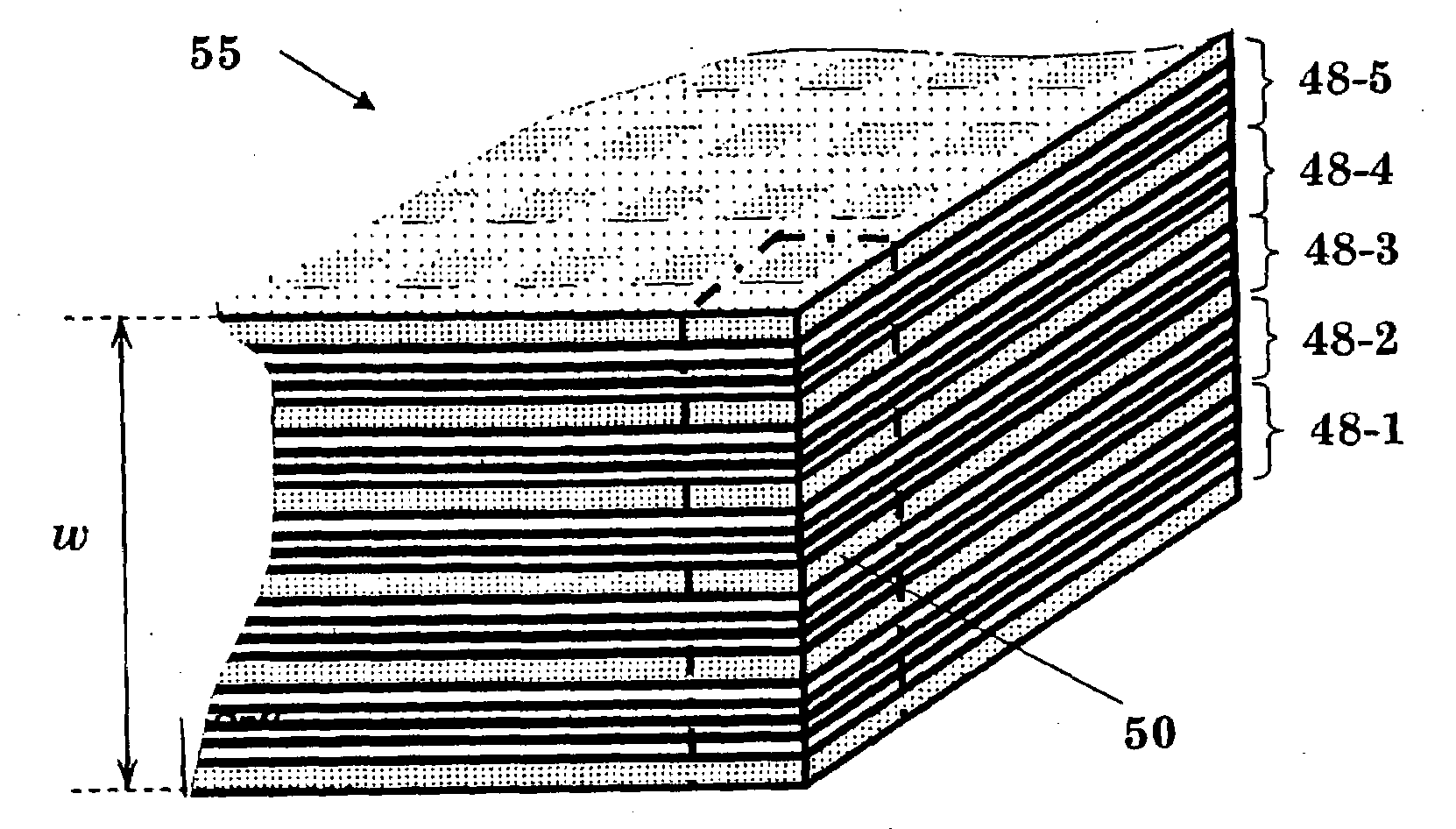
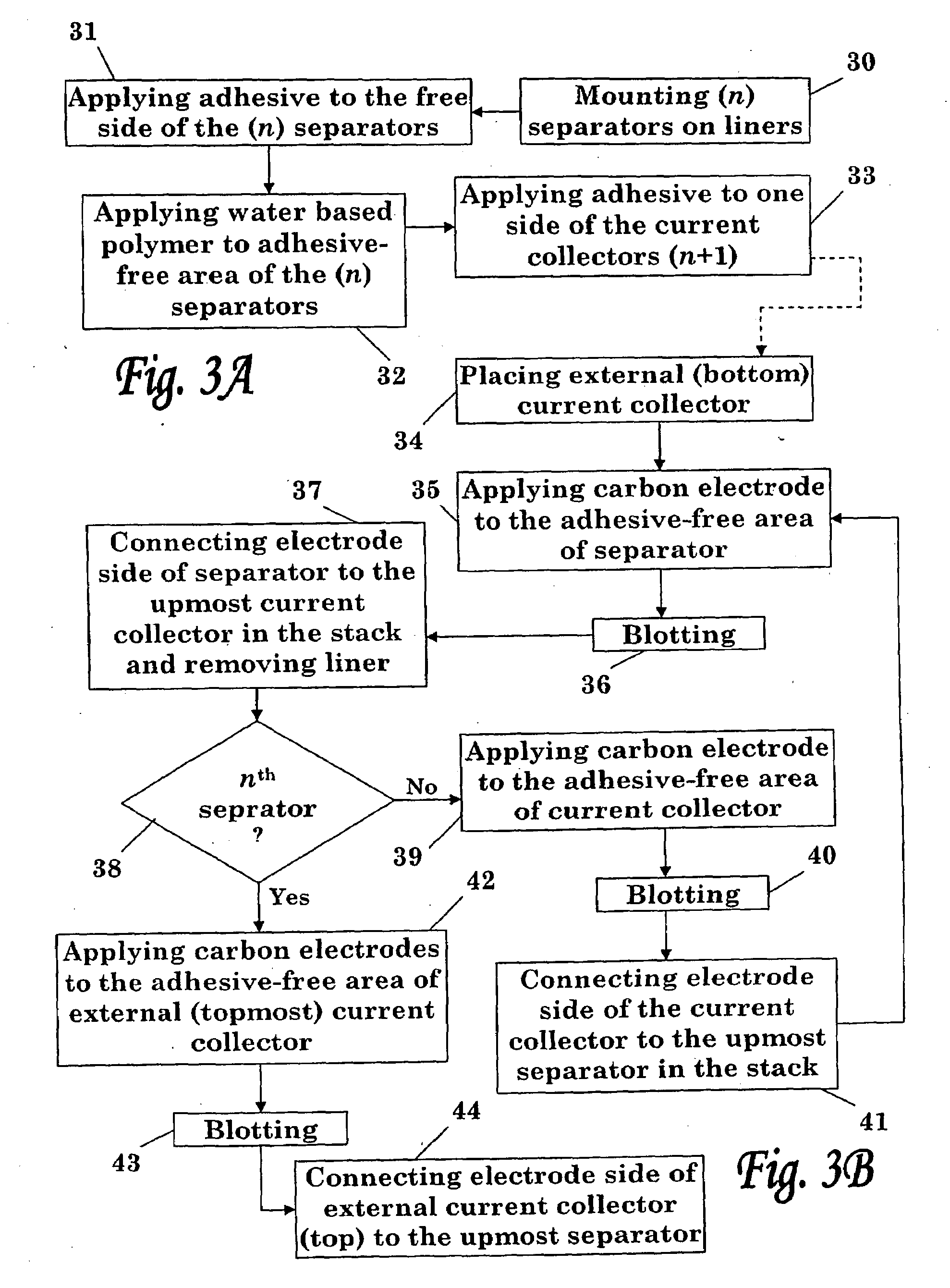
[0030]The present invention is directed to a multilayered energy storage device and to a method of its manufacture. More particularly, the present invention is directed to a bipolar capacitor constructed from a stack of n+1 current collectors and n separators disposed therebetween, wherein an electrode is attached to n current collectors and n separators (wherein n is an integer, n>=1) of the stack.

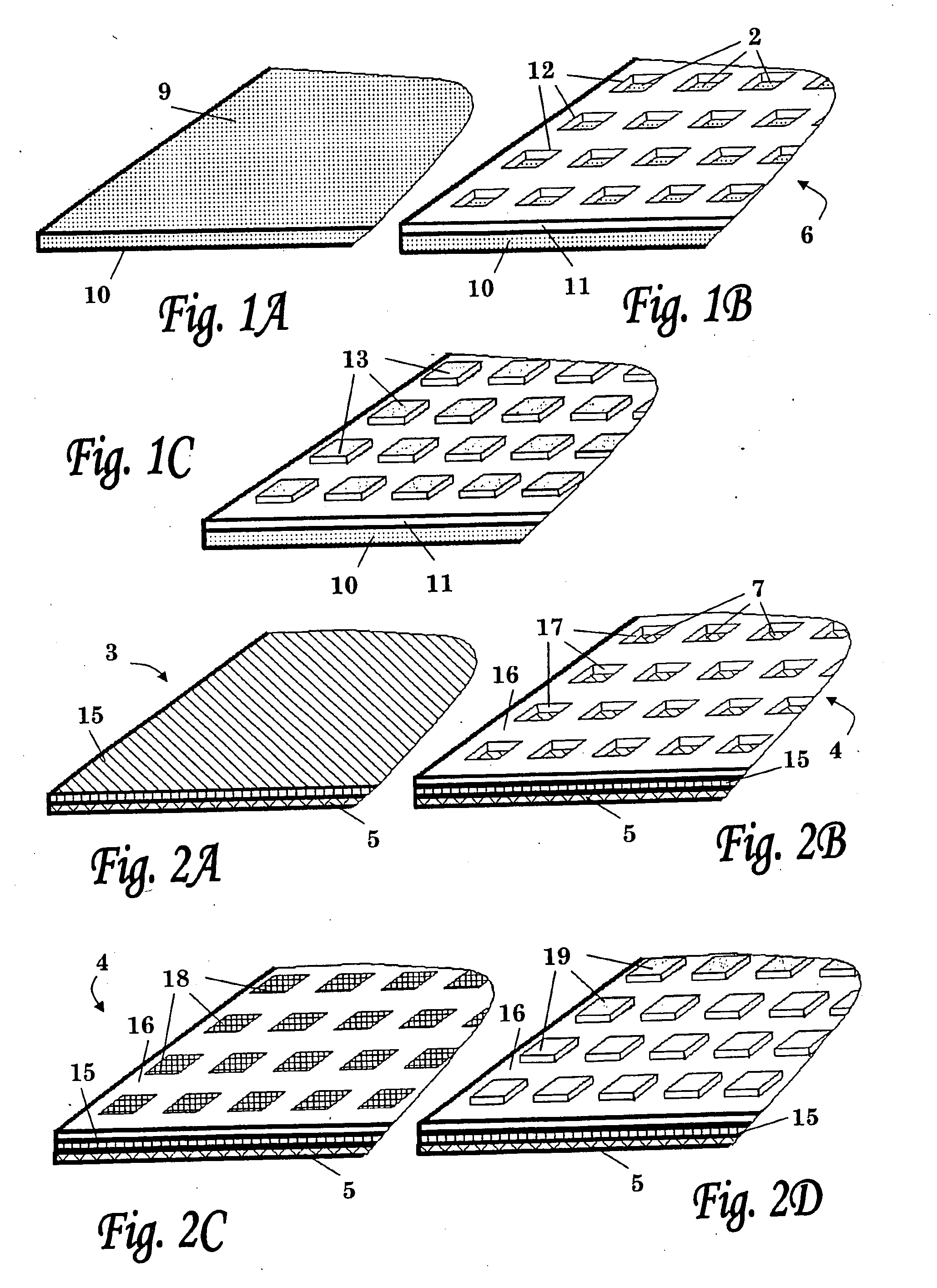
[0031]Current collectors to be used according to the present invention are made of a conductive material that is chemically inert to the aqueous electrolyte contained in the electrode. The current collector may be provided in the form of a metal foil, such as aluminum foil, plated metal or metal coated with a protective oxide. Alternatively, the current collector is a polymeric or a co-polymeric sheet, such as polyethylene or polytetrafluoroethane (Teflon), rubber or PVC (polyvinylchloride) loaded with conductive particles such as carbon black, graphite, metallic or plated metallic partic...


PUM

PropertyMeasurementUnit
thicknessaaaaaaaaaa
thickaaaaaaaaaa
thickaaaaaaaaaa

Abstract

An energy storage device comprising one or more cells, wherein each cell is defined by a pair of electrodes and a separator placed therebetween, wherein each cell is bounded by two current collectors, the geometric form and size of said separator being identical to the form and size of said current collectors, and wherein in each cell, one electrode is printed on one of said two current collectors and the other electrode is printed on one face of the separator, the two electrodes being electronically insulated by means of said separator, and wherein the peripheral region of the separator, which surrounds the electrode printed thereon, is sealed.

Description

FIELD OF THE INVENTION[0001]The present invention relates to energy storage devices, and specifically, to a multilayered electrochemical energy storage devices and to a method for manufacturing the same. More particularly, the invention relates to a method for manufacturing multilayered electrochemical capacitors or batteries comprising printable electrodes.BACKGROUND OF THE INVENTION[0002]A single cell energy storage device typically consists of two conducting plates (hereinafter current collectors) and an electronically insulating layer (dielectric, hereinafter separator) disposed therebetween. Electrodes are usually disposed between the current collectors and the separator and a liquid electrolyte (e.g., sulfuric acid) contained therein is used as a charge accumulation interface.[0003]Electrochemical energy storage devices (e.g., primary or secondary batteries, electrochemical cells such as fuel cells) are generally divided into two distinct categories, according to the type of e...

Claims


Application Information

Patent Timeline
Patent Type & Authority Applications(United States)
IPC IPC(8): H01G9/155B32B37/02H01G9/02H01M50/463
CPCH01G9/02H01G9/155H01M2/18Y02E60/13H01M6/40H01M10/0436H01M4/70Y02E60/10H01M50/463H01G11/28H01G11/52H01G11/80H01G11/12
Inventor LANG, JOEL
Owner CELLERGY
Why Eureka
Try Eureka