Cooling system for electronic equipment
a technology for electronic equipment and cooling system, which is applied in the direction of electrical apparatus casing/cabinet/drawer, domestic cooling apparatus, instruments, etc., can solve problems such as system stoppage, and achieve the effects of efficient cooling, low running cost, and precise operation
- Summary
- Abstract
- Description
- Claims
- Application Information
AI Technical Summary
Benefits of technology
Problems solved by technology
Method used
Image
Examples
first embodiment
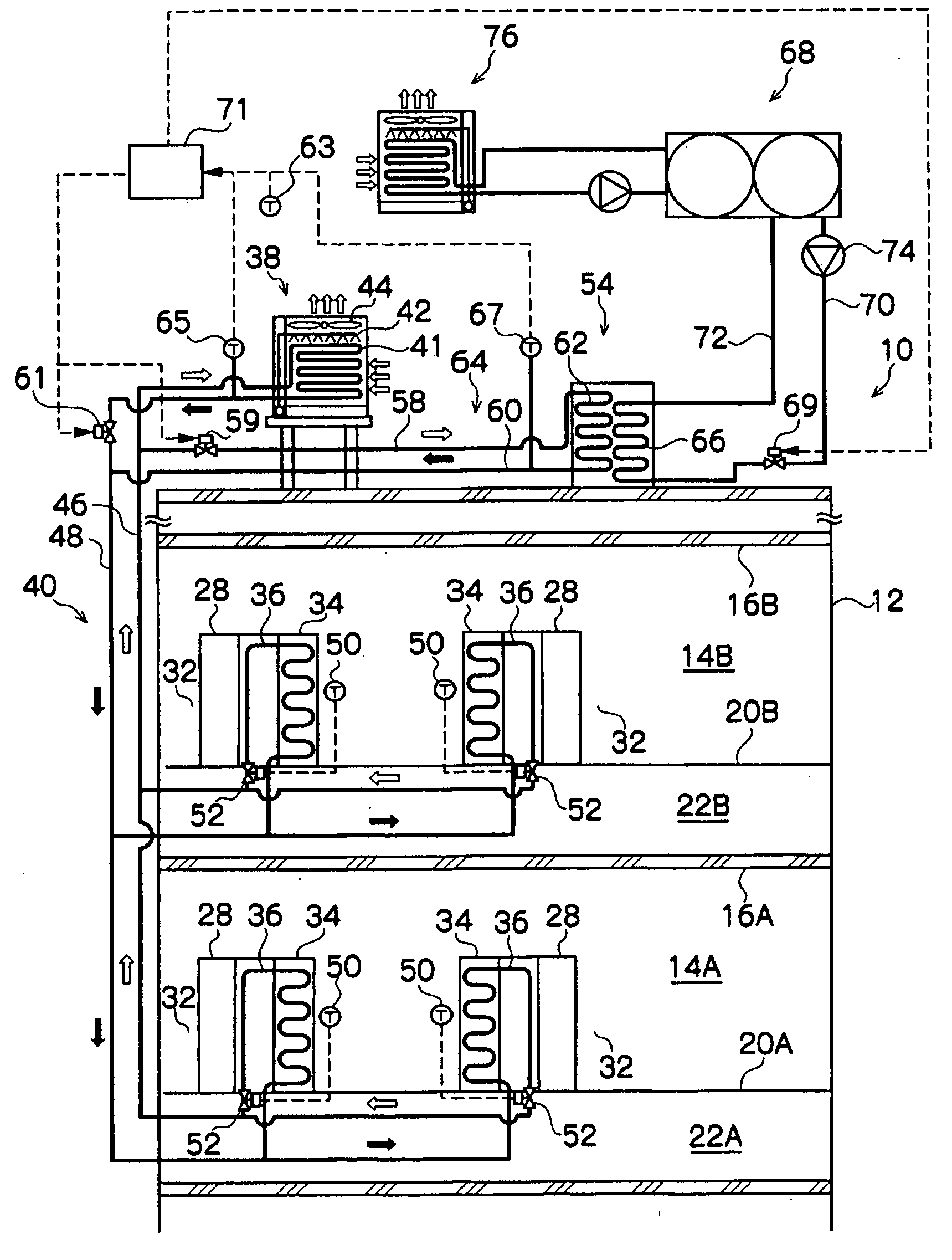
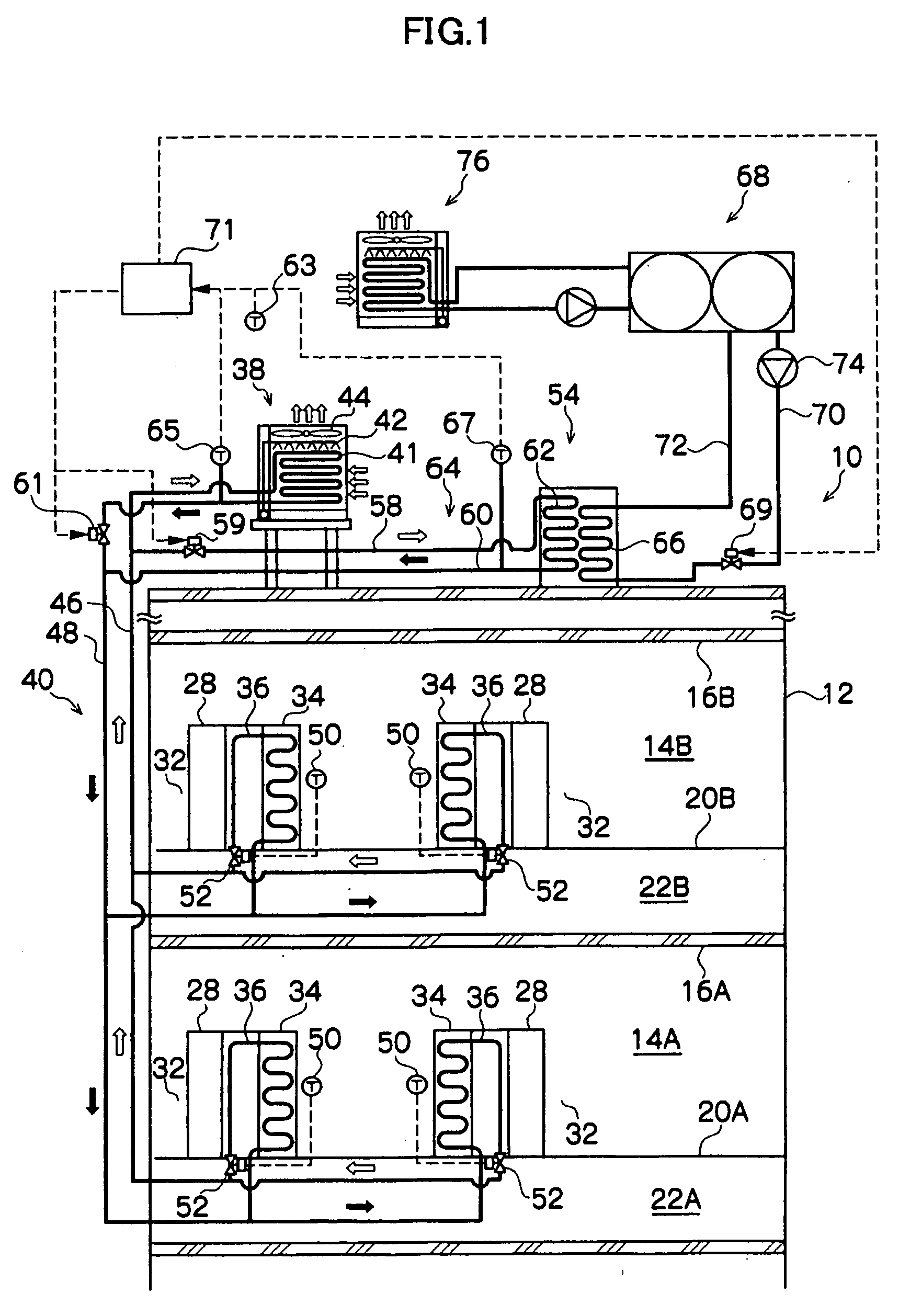
[0054]FIG. 1 is a conceptual view showing a cooling system 10 for an electronic device of a first embodiment of the present invention.
[0055]As shown in FIG. 1, in a two-storied building 12, server rooms 14A and 14B are formed in a first floor and a second floor respectively. Underfloor chambers 22A and 22B are respectively formed on the back sides of floor surfaces 20A and 20B on the first floor and the second floor. A plurality of air outlet ports (not illustrated) are disposed in the floor surfaces 20A and 20B. Cold air from air-conditioning machines 78 (see FIG. 3) which will be described later is blown into the server rooms 14A and 14B from the floor surfaces 20A and 20B through the underfloor chambers 22A and 22B. The air outlet ports are preferably disposed in the vicinity of the front surface side of each of servers 28, and the cold air blown from them is supplied to the servers 28, whereby the servers 28 can be efficiently cooled.
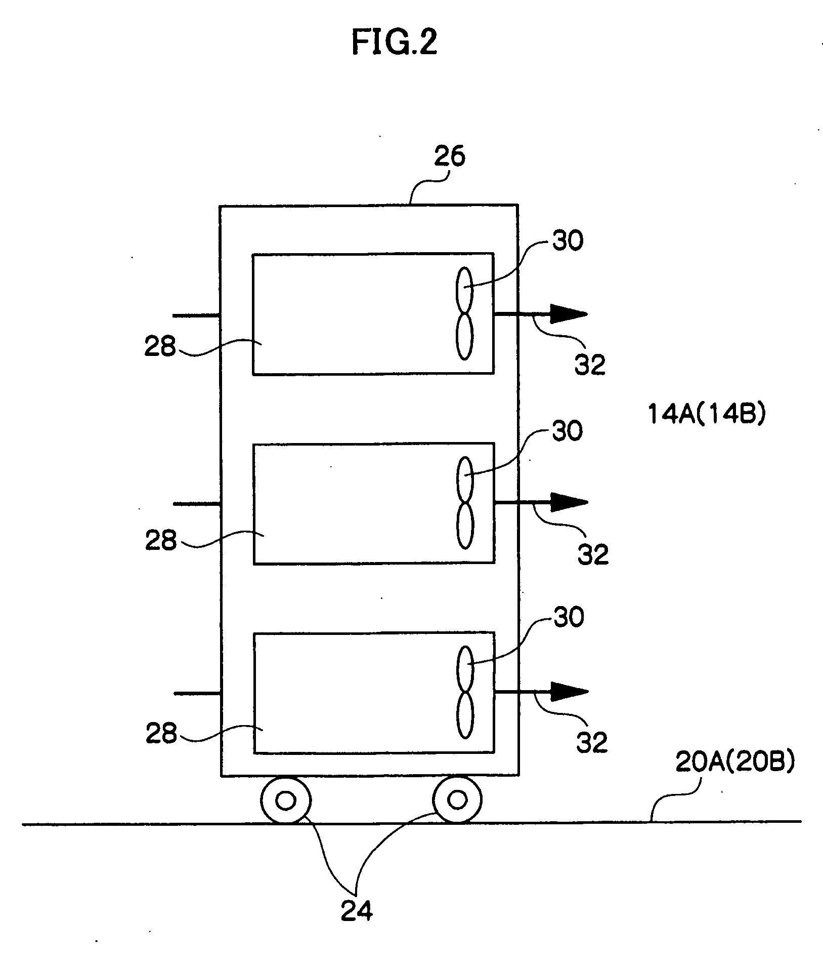
[0056]As shown in FIG. 2, server racks 26 are...
second embodiment
[0074]FIG. 3 is a conceptual view showing a cooling system 100 for an electronic device of a second embodiment of the present invention. The same members and constitutions as those in the first embodiment will be omitted.
[0075]In the cooling system 100 of the second embodiment, an air-conditioning machine 78 for cooling server rooms 14A and 14B is provided in the constitution of the cooling system 10 of the first embodiment, and the refrigerant of the circulation line 40 is used as a cold heat source of the air-conditioning machine 78.
[0076]More specifically, as shown in FIG. 3, machine rooms 80A and 80B are respectively provided adjacently to the server rooms 14A and 14B, and the air-conditioning machines 78 are installed in the machine rooms 80A and 80B, respectively. Further, inlet ducts 79 which take the air of the server rooms 14A and 14B into the air-conditioning machine 78 via the machine rooms 80A and 80B are placed by being penetrated through partition walls 82 which partit...
third embodiment
[0081]FIG. 4 is a conceptual view showing a cooling system 200 for an electric device of a third embodiment of the present invention. Explanation of the same members and constitutions as those in the second embodiment will be omitted.
[0082]The cooling system 200 of the third embodiment has the constitution in which a plurality of servers 28 equipped with the evaporators 34 are divided into groups, and thereby, the cooling system 200 can be operated with the groups being edge-cut from each other, in addition to the constitution of the cooling system 100 of the second embodiment.
[0083]More specifically, as shown in FIG. 4, a plurality of the servers 28 equipped with the evaporators 34 are divided into a plurality of groups. In the case of FIG. 4, the servers 28 installed in the server room 14A on the first floor are grouped as one group, and the servers 28 installed in the server room 14B on the second floor are grouped as another group. The method for grouping is not limited to the a...
PUM
 Abstract
Description
Claims
Application Information
 - R&D
- Intellectual Property
- Life Sciences
- Materials
- Tech Scout
- Unparalleled Data Quality
- Higher Quality Content
- 60% Fewer Hallucinations
Browse by: Latest US Patents, China's latest patents, Technical Efficacy Thesaurus, Application Domain, Technology Topic, Popular Technical Reports.
© 2025 PatSnap. All rights reserved.Legal|Privacy policy|Modern Slavery Act Transparency Statement|Sitemap|About US| Contact US: help@patsnap.com


