
Digital television transmission and receiving apparatus and method using 1/4 rate coded robust data

Active Publication Date: 2009-08-13
ELECTRONICS & TELECOMM RES INST
View PDF9 Cites 99 Cited by
  • Summary
  • Abstract
  • Description
  • Claims
  • Application Information

AI Technical Summary

Benefits of technology

[0038]As described above, the present invention can reduce a signal-to-noise ratio (SNR) satisfying a Threshold of Visibility (TOV) by performing additional Forward Error Correction (FEC) on robust data and transmitting and receiving ¼-rate-coded robust data to transit one-bit data on two symbols and thus improving decoding performance in an equalizer and a trellis decoder of a receiver.

Problems solved by technology

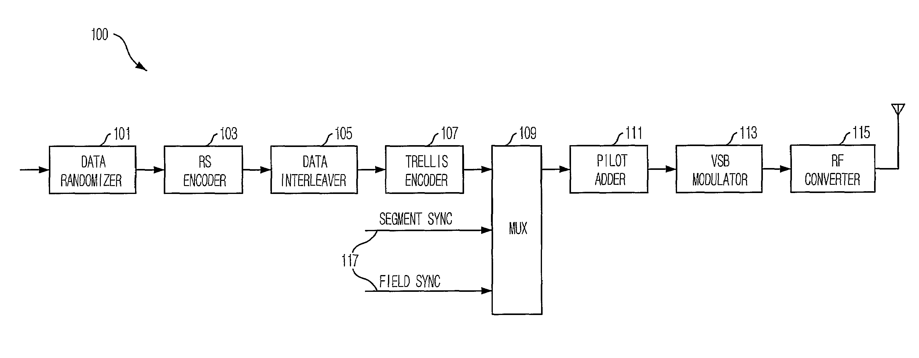
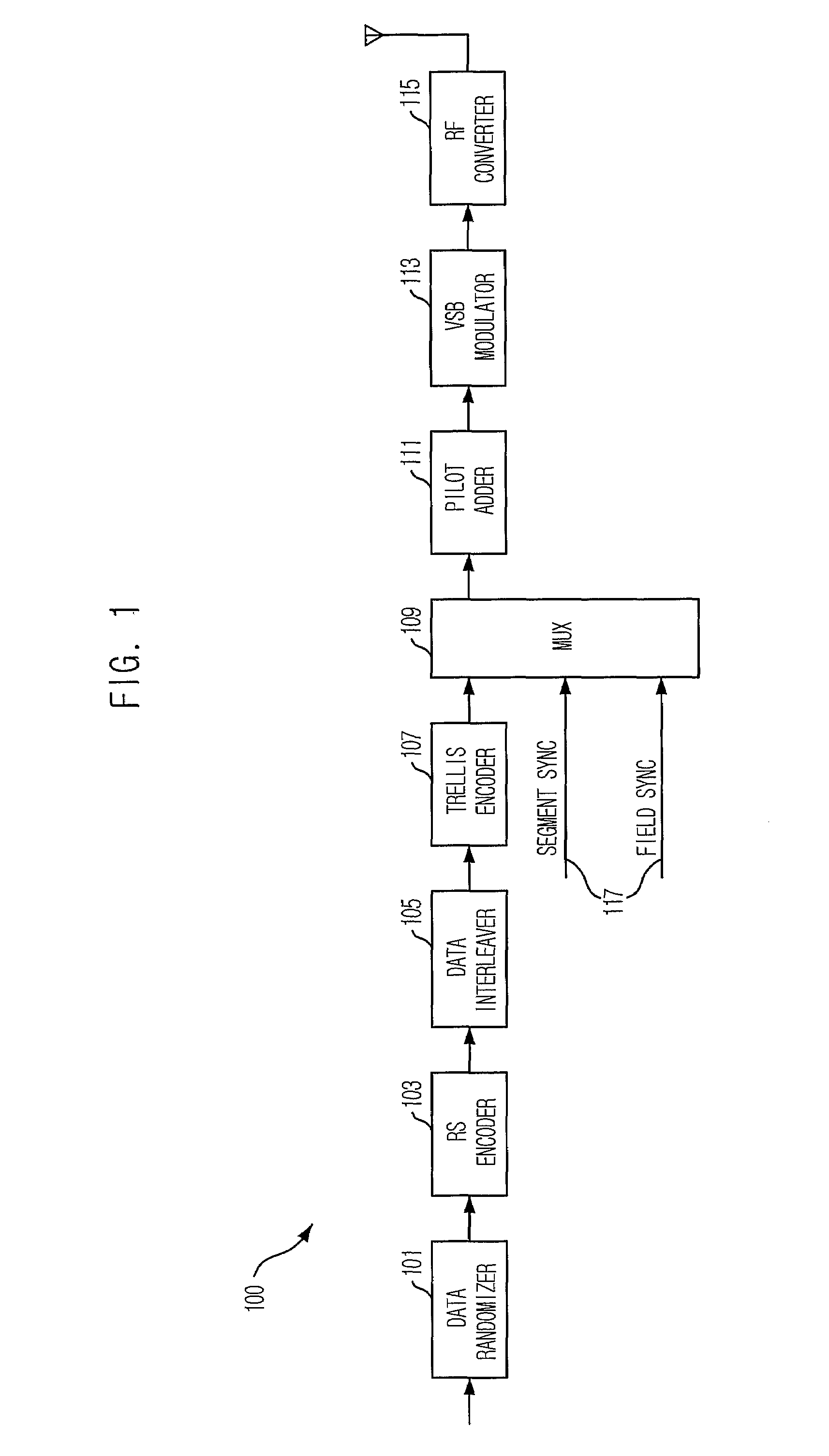
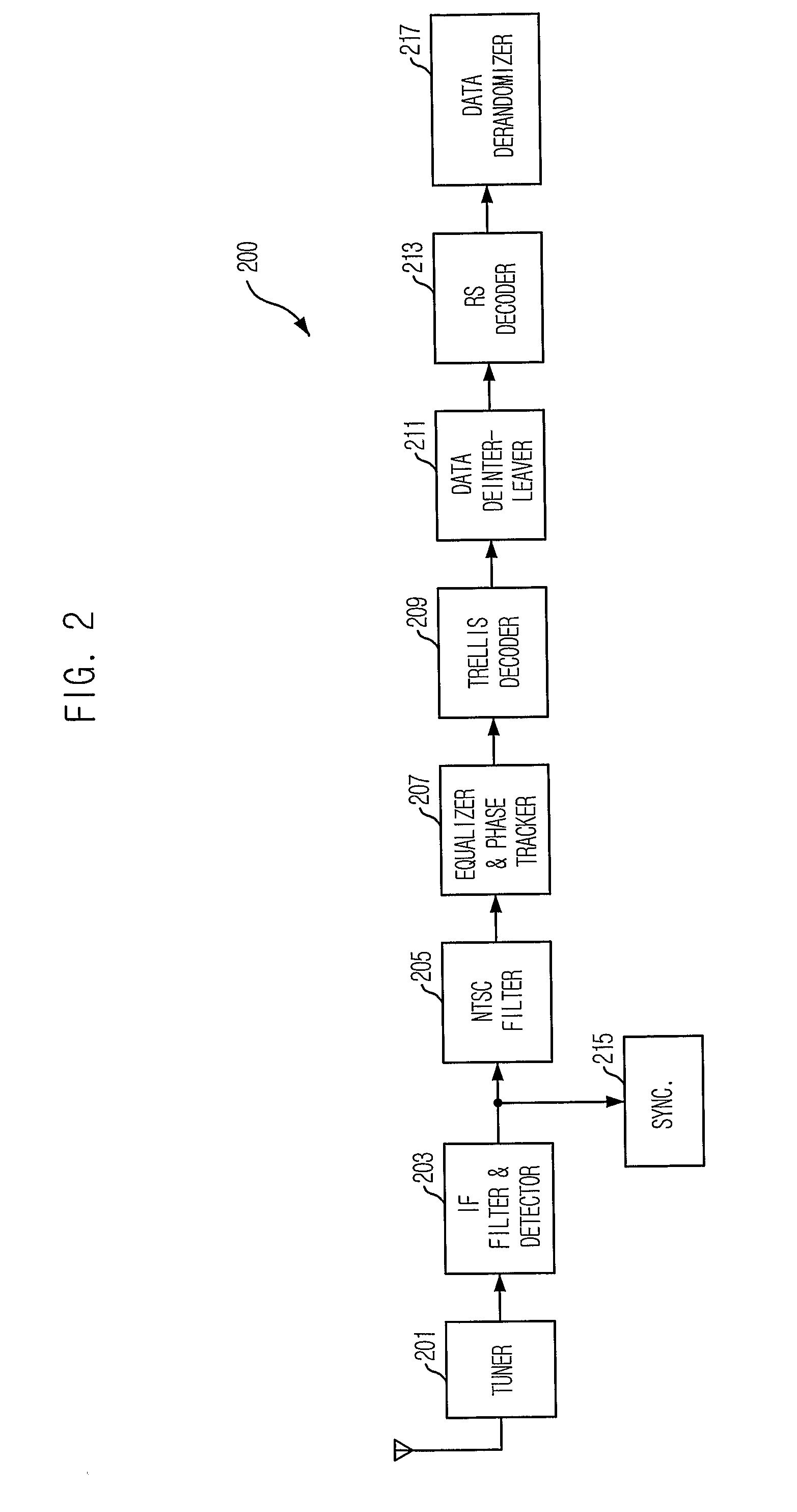
However, transmission signals of a conventional 8-VSB transceiver are distorted in indoor and mobile channel environments due to variable channel and multipath phenomena, and this degrades reception performance of the receiver.
In other words, transmitted data are affected by various channel distortion factors.
Since an equalizer of the receiver does not have a convergence speed fast enough to compensate for the distortion of receiving signals, which occurs by the change in multipath characteristics and the Doppler interference, the receiver cannot perform equalization precisely.
For this reason, the broadcasting program reception performance of 8-VSB DTV broadcast is lower than that of an analog broadcast and reception is impossible in a mobile receiver.
Even if reception is possible, there is a problem that a signal-to-noise ratio (SNR) satisfying Threshold of Visibility (TOV) increases.
Although the transmitted robust data show a better reception performance than normal data, it is still hard to secure data reception in a poor channel environment such as an environment where a user is walking or moving.

Method used


Image

  • Digital television transmission and receiving apparatus and method using 1/4 rate coded robust data
  • Digital television transmission and receiving apparatus and method using 1/4 rate coded robust data
  • Digital television transmission and receiving apparatus and method using 1/4 rate coded robust data

Examples


Embodiment Construction

[0068]Other objects and aspects of the invention will become apparent from the following description of the embodiments with reference to the accompanying drawings, which is set forth hereinafter. If it is considered that further description on the prior art may blur the points of the present invention, the description will not be provided. Hereinafter, preferred embodiments of the present invention will be described in detail with reference to the accompanying drawings.

[0069]FIG. 4 is a block diagram showing a Digital Television (DTV) transmitter in accordance with an embodiment of the present invention. As shown, the transmitter 400 includes: a first multiplexer 401, a data randomizer 403, a Reed Solomon (RS) encoder 405, a robust interleaver / packet formatter 407, a data interleaver 409, a robust encoder 411, a robust data processor 413, a trellis encoder 415, a second multiplexer 417, and a pilot adder / modulator / Radio Frequency (RF) converter 419.

[0070]The data randomizer 403, th...


PUM


Abstract

Provided is a Vestigial Side Band Digital Television (DTV) transmitter / receiver based on Advanced Television System Committee A / 53. The invention provides DTV transmitter / receiver having a dual stream structure through generation of robust data which has a transmission rate a fourth as fast as that of normal data, and a method thereof. The DTV transmitter includes: input means for receiving digital video data stream including normal and robust data; encoding means for performing ¼ rate coding on the digital video data stream so that one bit can be transmitted through two symbols; and transmitting means for modulating / transmitting output signals of the encoding means. This invention can reduce SNR and satisfy TOV of robust data by performing additional FEC on robust data, transmitting / receiving ¼ rate coded robust data, which are capable of transmitting one-bit data for two symbols, and improving decoding ability of an equalizer and a trellis decoder of a DTV receiver.

Description

TECHNICAL FIELD[0001]The present invention relates to a Vestigial Side Band (VSB) digital television (DTV) transmitter and receiver based on a DTV standard A / 53 of the Advanced Television System Committee (ATSC), and a method thereof. More particularly, it relates to a DTV transmitter and receiver having a double stream structure by generation of robust data having a transmission rate of a fourth as fast as normal data, and a method thereof.BACKGROUND ART[0002]The standards of the Advanced Television System Committee (ATSC) suggest to use a signal obtained by modulating 12 independent data streams, which are trellis encoded and time-multiplexed, into 10.76 MHz-rate 8-level Vestigial Side Band (VSB) symbol streams to transmit High Definition Television (HDTV) broadcasting through a terrestrial broadcasting channel. The frequency band of the signal is transformed into a frequency band of 6 MHz which corresponds to a standard Very High Frequency (VHF) or Ultrahigh Frequency (UHF) terre...

Claims


Application Information

Patent Timeline
IPC IPC(8): H04N7/12H04N5/38H04N7/173H04N5/00H04N7/24
CPCH04N21/2383H04N21/4382H04N19/61H04N7/015
Inventor KIM, SUNG-HOONJI, KUM-RANLEE, JAE-YOUNGKIM, SEUNG-WONLEE, SOO-INAHN, CHIETEUK
Owner ELECTRONICS & TELECOMM RES INST
Learn More