Platform cooling structure for gas turbine moving blade

a technology of moving blades and cooling structures, which is applied in the direction of machines/engines, mechanical equipment, liquid fuel engines, etc., can solve the problems of inability to obtain sufficient cooling performance, inability to control the temperature of the sealing air, and inability to achieve sufficient cooling performance, so as to reduce the weight of the projecting part, and improve the reliability of the moving blad

Active Publication Date: 2009-08-13
MITSUBISHI POWER LTD
View PDF8 Cites 48 Cited by
  • Summary
  • Abstract
  • Description
  • Claims
  • Application Information

AI Technical Summary

Benefits of technology

[0026]As a result, since it is possible to form the cooling communication hole up to a portion of the platform away from the moving blade cooling passageways without particularly attaching an additional member such as a cover plate to the platform, it is possible to guide the high-pressure cooling air, flowing to the moving blade cooling passageways, to the upper surface of the side edge and to improve the reliability of the moving blade.
[0027]Preferably, an projecting part may be formed at a portion where a lower surface of the platform intersects an outer surface of the shank part; and the cooling communication holes may be formed through the inside of the shank part, the platform, and the projecting part. According to the invention, since it is possible to form the cooling communication hole up to a portion of the platform away from the moving blade cooling passageways without particularly attaching the additional member such as the cover plate to the platform, it is possible to guide the high-pressure cooling air, flowing to the moving blade cooling passageways, to the upper surface of the side edge and to improve the reliability of the moving blade.
[0028]Further, the projecting part having the cooling communication holes formed therein may protrude in a convex shape; and the projecting part and the cooling communication hole may be formed upon forming the platform and the shank part by casting. Accordingly, since the projecting part is formed in only a portion where the cooling communication hole is provided, it is possible to realize a decrease in weight of the projecting part and to manufacture the cooling communication hole in a simple manner.
[0029]Further, in the platform cooling structure for the gas turbine moving blade with the above-described configuration, a plurality of rows of the discharge openings may be formed in an upper surface in the vicinity of the side edge of the platform so as to be disposed along the side edge. According to the invention, since the discharge opening is broadly provided in the upper surface in the vicinity of the side edge of the platform, the surface in the vicinity of the front end of the platform is effectively cooled by the high-pressure cooling air flowing to the moving blade cooling passageways, thereby obtaining the higher cooling performance and cooling the broader area.
[0030]As described above, according to the invention, it is possible to obtain the platform cooling structure for the gas turbine moving blade capable of improving the cooling performance of the platform and of improving the reliability of the moving blade in such a manner that a portion in the vicinity of the side edge of the platform which is away from the moving blade cooling passageways and is easily influenced by the thermal stress caused by the high-temperature combustion gas, that is, the upper surface of the side edge is effectively cooled by guiding the high-pressure cooling air, flowing to the moving blade cooling passageways, to the discharge opening formed in a surface of the platform in the vicinity of the side edge of the platform without particularly attaching the additional member such as the cover plate described in Patent Document 3 to the platform.

Problems solved by technology

However, since the sealing air is supplied from the lower surface of the platform in order to prevent the high-temperature combustion gas from leaking from a gap between the adjacent platforms to the rotor, in general, a temperature of the sealing air is not controlled and moreover, a pressure of the sealing air is not controlled at high pressure.
As a result, it is not possible to obtain the sufficient cooling performance just by cooling the platform by the use of the sealing air.
Particularly, since a portion in the vicinity of the side edge of the platform away from the bottom of the blade is away from the moving blade cooling passageway 019 for cooling the inside of the blade, it is difficult to cool the portion.
For this reason, it is possible to cool and seal the end surface of the platform 020, but a problem arises in that it is not possible to effectively cool the upper surface of the platform in the vicinity of the side end portion exposed to the high-temperature combustion gas.
As a result, a problem arises in that the processes of assembling increase.

Method used


Image

  • Platform cooling structure for gas turbine moving blade
  • Platform cooling structure for gas turbine moving blade
  • Platform cooling structure for gas turbine moving blade

Examples


first embodiment

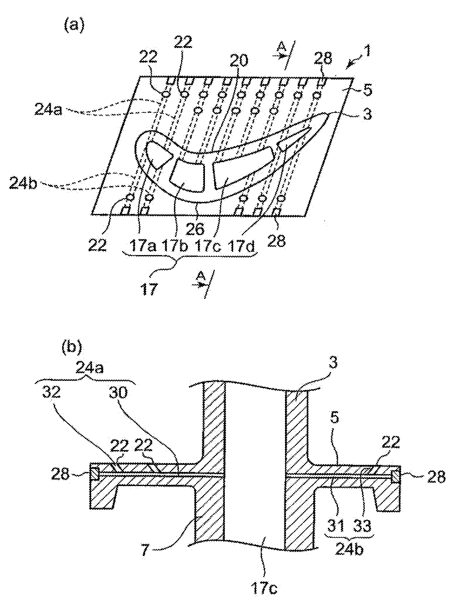
[0048]As shown in FIG. 1, the platform 5 is formed in a substantially rectangular shape in a top view. The blade part 3 is integrally formed with the platform 5 by casting. In the inside of the blade part 3, the moving blade cooling passageways 17 are provided as a leading edge portion 17a, center portions 17b, 17c, and a trailing edge portion 17d. Then, cooling air is introduced from the blade root part 9 into the passageways. Although it is not shown in the drawing, a part or a whole part of the passageways communicate with one another in the inside of the blade so as to form a serpentine cooling passageway and to cool the whole part of the blade part3.

[0049]In a surface of the platform 5 in the vicinity of the side edge on a concave side 20 of the platform 5, a plurality of cooling air discharge openings 22 is provided along the side edge, and a cooling communication hole 24a is provided of which one end communicates with the moving blade cooling passageways 17a, 17b, 17c, or 17d...

second embodiment

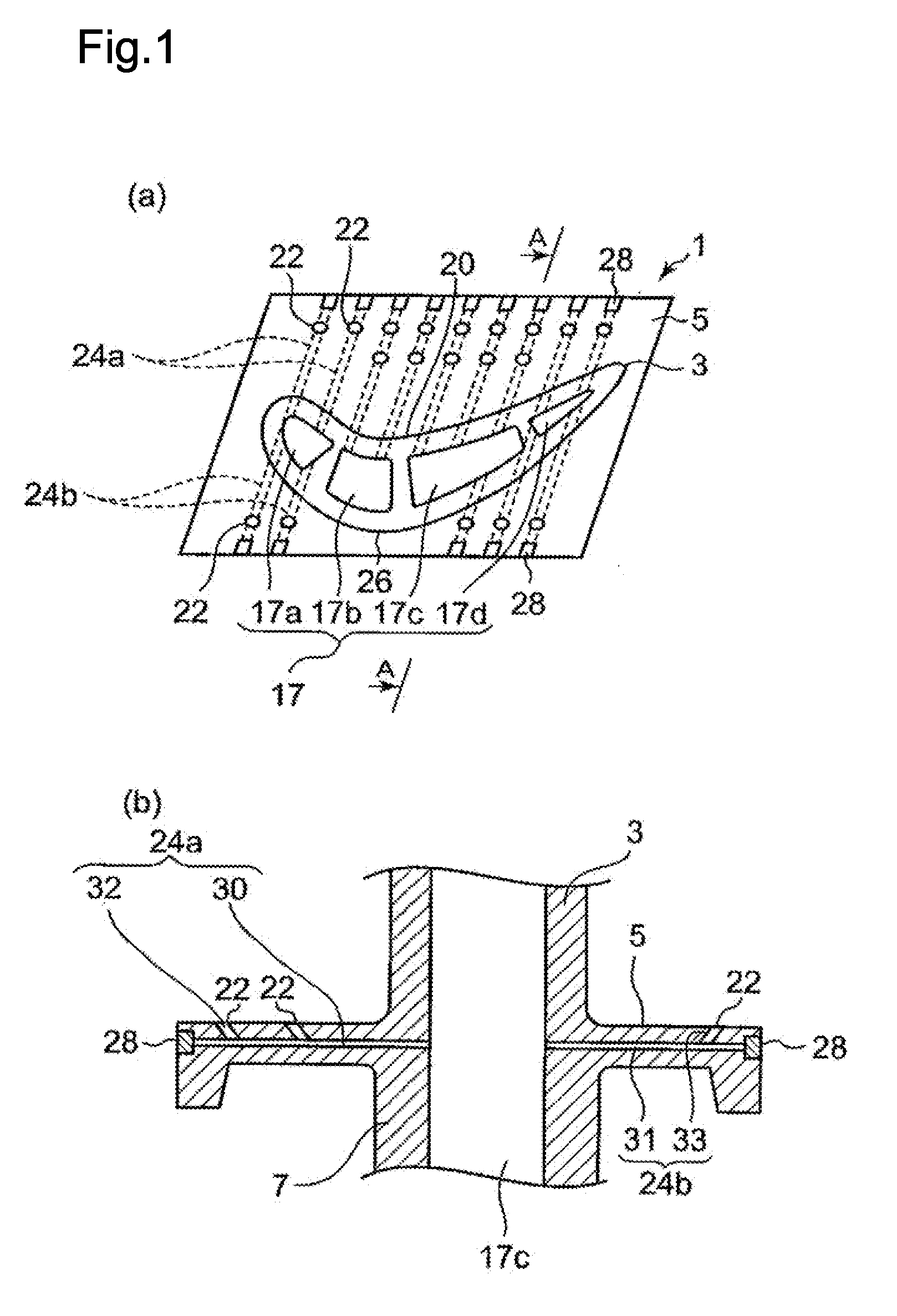
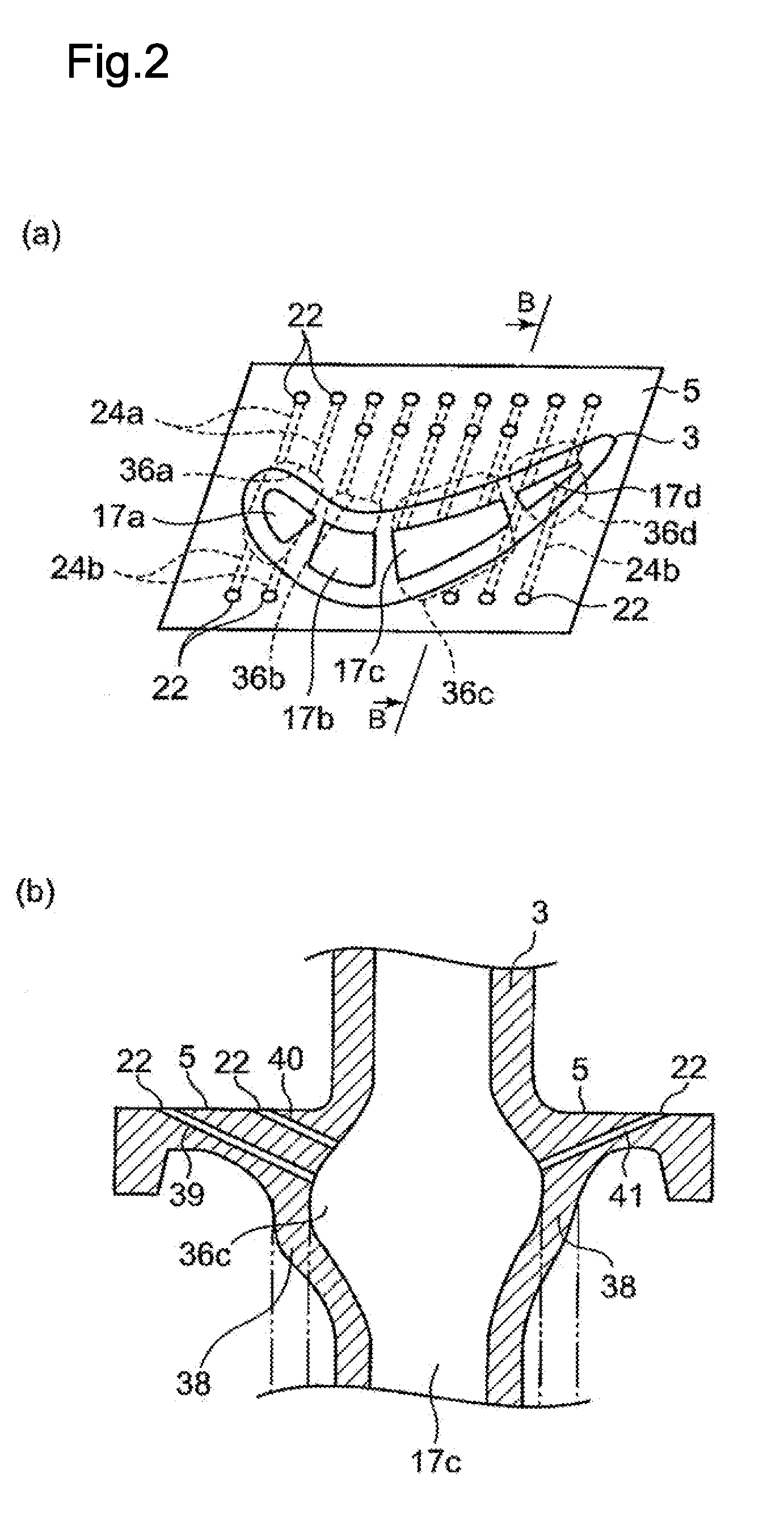
[0057]Next, a second embodiment will be described with reference to FIG. 2.

[0058]The same reference numerals are given to the same components as those of the first embodiment, and the description thereof will be omitted. In the second embodiment, cooling passageway swollen parts 36a, 36b, 36c, and 36d are formed in such a manner that the moving blade cooling passageways 17a, 17b, 17c, and 17d of the shank part 7 are swollen toward the side edge of the platform 5.

[0059]Since the cooling passageway swollen parts 36a, 36b, 36c, and 36d are formed as shown in FIG. 2(b), the shank part 7 is swollen outward, and cooling communication holes 39, 40, and 41 are formed through the inside of the platform 5 and a swollen shank part 38 in a linear shape.

[0060]The platform 5 on the concave side 20 is provided with the outer cooling communication hole 39 and the inner cooling communication hole 40, and the platform 5 on the convex side 26 is provided with the cooling communication hole 41.

[0061]Ad...

third embodiment

[0066]A third embodiment will be described with reference to FIG. 3.

[0067]The same reference numerals are given to the same components as those of the first embodiment, and the description thereof will be omitted. In the third embodiment, as shown in FIG. 3(b), an projecting part 43 is formed at a portion where the lower surface of the platform 5 intersects the outer surface of the shank part 7, and cooling communication holes 45, 46, and 47 are formed through the inside of the shank part 7, the platform 5, and the projecting part 43 in a linear shape.

[0068]Then, as shown in FIG. 3(c), the projecting part 43, in which the cooling communication hole 45 is formed, protrudes in a convex shape. The projecting part 43 and the cooling communication hole 45 are simultaneously formed upon forming the platform 5 and the shank part 7 by casting. The projecting part 43 is formed in a portion having an projection necessary for forming the cooling communication hole 45 so that only the cooling c...


PUM


Abstract

A platform cooling structure for a gas turbine moving blade is provided which is capable of improving cooling performance of a platform and of improving reliability of a moving blade in such a manner that a portion in the vicinity of a side edge of the platform which is away from moving blade cooling passageways and is easily influenced by thermal stress caused by high-temperature combustion gas, that is, an upper surface of the side edge is effectively cooled by guiding high-pressure cooling air, flowing to the moving blade cooling passageways, to a discharge opening formed in a surface of the platform in the vicinity of the side edge of the platform without particularly attaching an additional member such as a cover plate to the platform. A moving blade cooling passageway 17c is formed in the inside of the gas turbine moving blade. Cooling communication holes 24a and 24b, of which one ends communicate with the moving blade cooling passageway 17c and the other ends communicate with a plurality of discharge openings 22 provided in the surface of the platform in the vicinity of the side edge of the platform 5, are formed through the inside of the platform.

Description

TECHNICAL FIELD[0001]The present invention relates to a platform cooling structure for a gas turbine moving blade.BACKGROUND ART[0002]An outline structure of a gas turbine moving blade is shown in FIG. 4. In this drawing, the gas turbine moving blade 1 includes a blade part 3 forming a blade, a platform 5 connected to a bottom of the blade part 3, and a shank part 7 located below the platform 5, where a blade root part 9 is formed below the shank part 7.[0003]Then, in FIG. 4, a continuous groove having a wave shape is formed in both side walls of the blade root part 9. A continuous groove having the same shape is formed in a rotor disk 11. By allowing the groove of the blade root part 9 to engage with the groove of the rotor disk 11, the gas turbine moving blade 1 is fixed to the rotor disk 11. Then, in the same fixing manner, a plurality of gas turbine moving blades 1 is adjacently fixed to the rotor disk 11 in a circumferential direction.[0004]Additionally, a cavity 13 is formed b...

Claims


Application Information

Patent Timeline
Patent Type & Authority Applications(United States)
IPC IPC(8): F01D5/18F01D25/12
CPCF01D5/18F05D2240/81F01D25/12F01D5/187F01D5/08F01D5/30F02C7/18
Inventor TORII, SHUNSUKEKUWABARA, MASAMITSUITO, EISAKU
Owner MITSUBISHI POWER LTD
Why Eureka
Try Eureka