
Substrate flat grinding device

a flat grinding and substrate technology, applied in grinding drives, grinding heads, manufacturing tools, etc., to achieve the effect of high rigidity, raised and lowered, and superior flat thickness distribution

Inactive Publication Date: 2009-08-13
OKAMOTO MACHINE TOOL WORKS LTD
View PDF19 Cites 52 Cited by
  • Summary
  • Abstract
  • Description
  • Claims
  • Application Information

AI Technical Summary

Benefits of technology

[0016]A second object of this invention is to apply water hydrostatic pressure bearing technology to the bearings of the grindstone spindle and workpiece spindle of a high-rigidity substrate flat grinding device, thus providing a substrate flat grinding device with water hydrostatic pressure bearings is environment friendly.
[0022]Also, compared with the conventional method which tilts the two shafts of the x-axis and y-axis of the columns to which the grindstone spindle is fastened so that it can be raised and lowered, and compared with the method which tilts the grindstone spindle at three air bearing points or four magnetic bearing points, the three fastening plate height position adjustment mechanisms of the invention make it easy to set the tilt angle of the grindstone spindle to the surface of the substrate, and it is accurate and has high rigidity.
[0023]If one uses a hollow spindle to shaft-support the rotary chuck table made of a porous ceramic and uses water hydrostatic pressure bearings for the bearings of the grindstone spindle, a substrate flat grinding device results that is environment friendly.
[0024]By making the grinding head structure in which a cup wheel type grindstone is shaft-supported on the wheel spindle that is rotated and moved linearly by composite actuators, during grinding a substrate, the substrate surface is cut into or retracted from by 0- to 1.5-mm advancement and retraction motions of the grindstone spindle, and for movement of the grinding head to the standby position, a fastening plate lifting and lowering mechanism having a kinematic coupling and cylinder rod is used, and because this is done by lifting or lowering the fastening plate, the time needed for grinding can be shortened.

Problems solved by technology

Also, the semiconductor manufacturing industry does not like to get oil on a substrate during substrate processing, and would like to see the appearance of substrate flat grinding devices with water hydrostatic pressure bearings.

Method used


Image

  • Substrate flat grinding device
  • Substrate flat grinding device
  • Substrate flat grinding device

Examples


Embodiment Construction

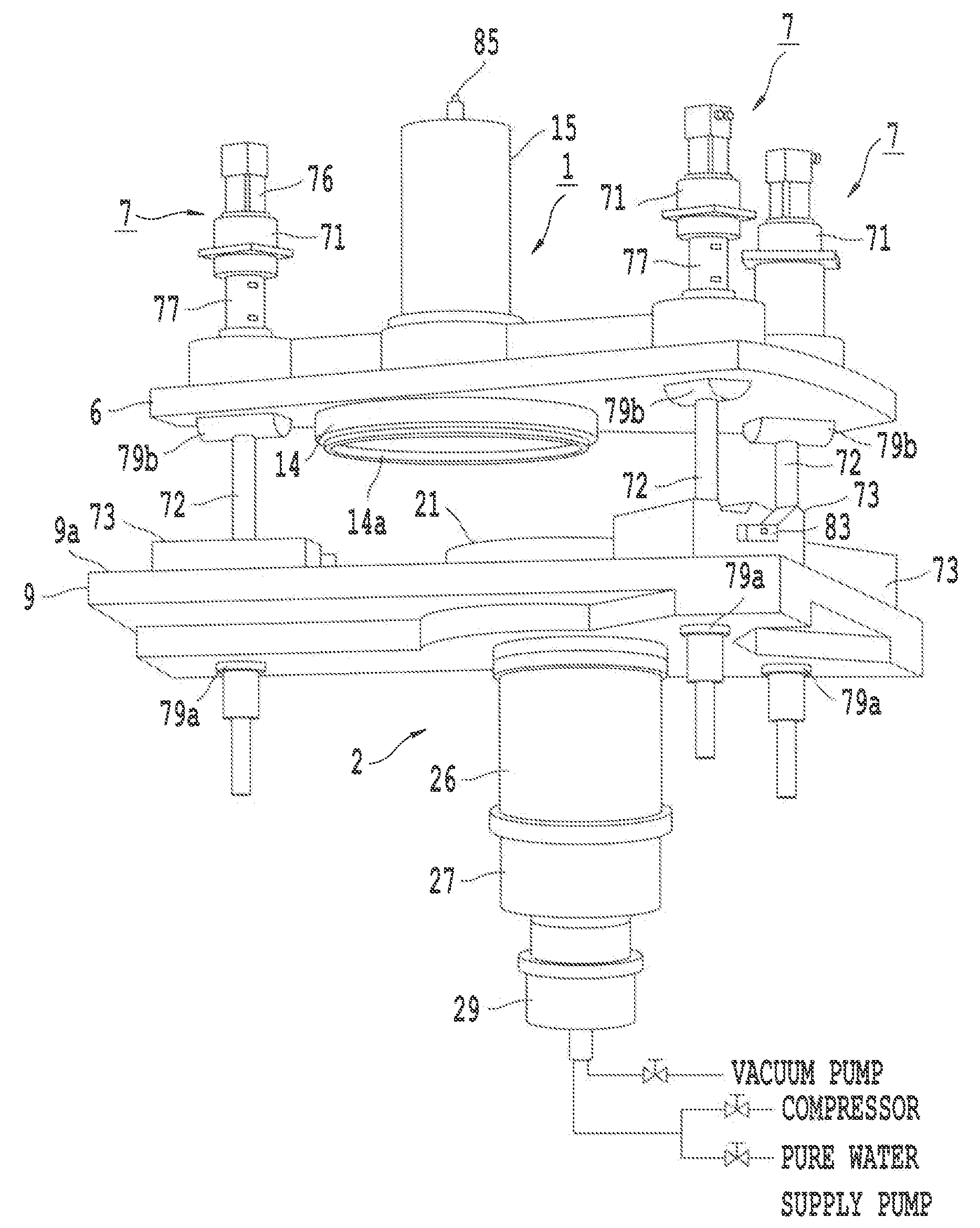
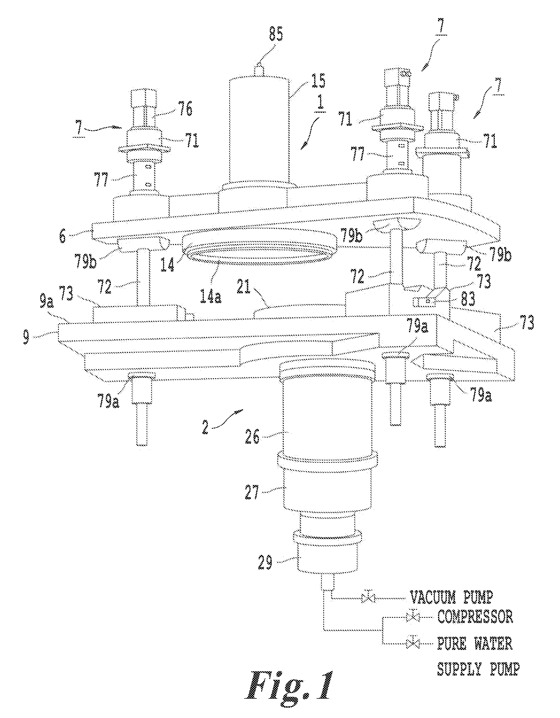
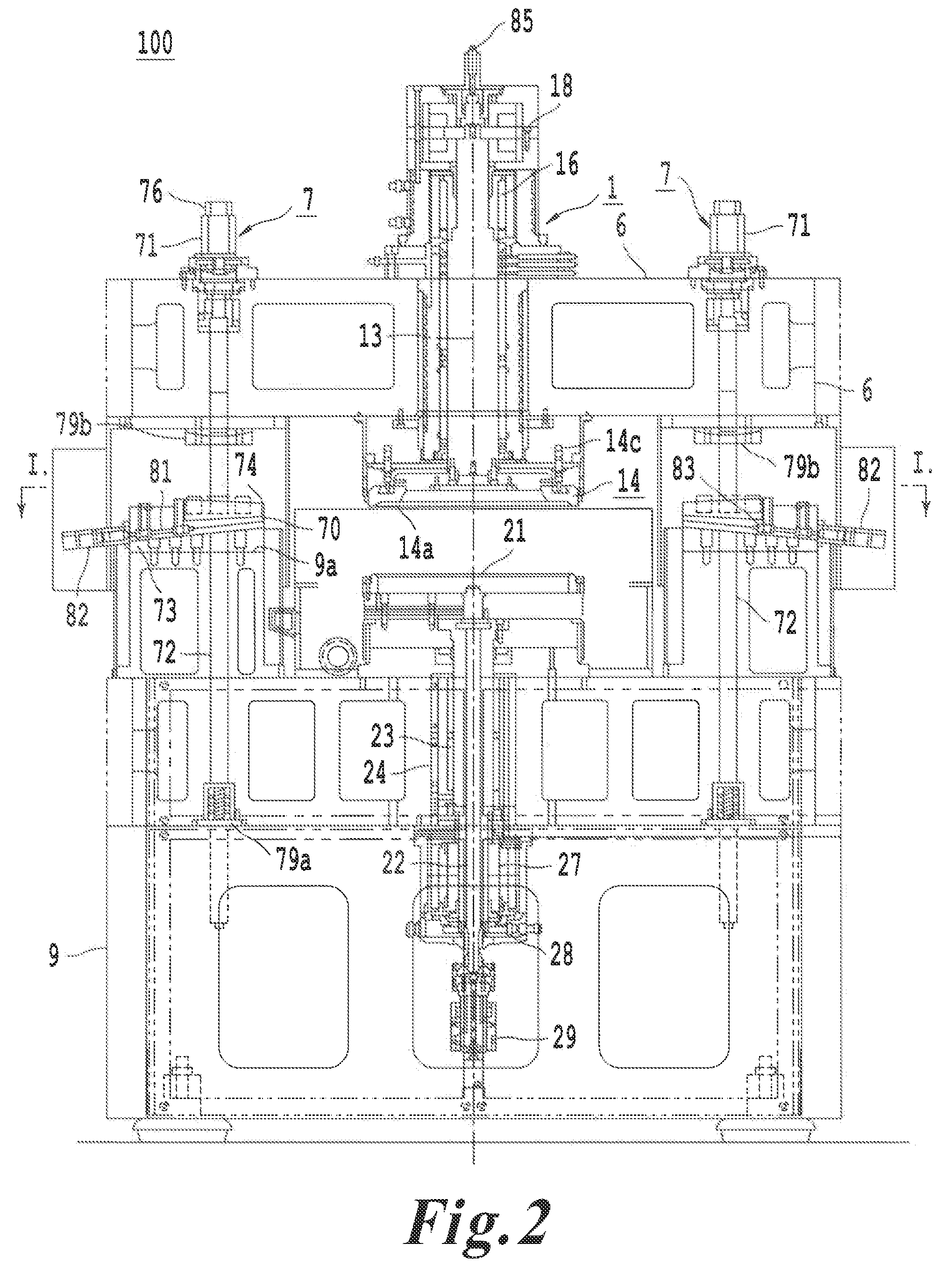
[0037]As shown in FIG. 1, FIG. 2, and FIG. 3, the substrate flat grinding device 100 of this invention is assembled mainly from a workpiece chuck table mechanism 2 that is provided in a central circular cavity of machine frame 9, a grinding head 1 that is supported with hydrostatic pressure bearings and magnetic bearings, so that it can rotate and move linearly, a cup wheel type grindstone 14 that is shaft-supported by a grindstone spindle 13 that is capable of rotary and / or linear motion, a rotary / linear motion composite actuator 16, 18 that causes the grindstone spindle 13 to execute rotary and / or linear motion, and three fastening plate lifting-and-lowering mechanisms 7. Each of the three three fastening plate lifting-and-lowering mechanisms has a kinematic coupling and cylinder rod that raise and lower the fastening plate 6 at three points of the vertices of an equilateral or isosceles triangle. The grinding head 1 is fixed at the center of the lower surface of the fastening pla...


PUM


Abstract

To provide a high-rigidity flat grinding device, a substrate flat grinding device has three fastening plate lifting-and-lowering mechanisms that have kinematic couplings and a cylinder rod that move the fastening plate upward or downward. Being a high-rigidity grinding device in which the load of the fastening plate 6 also is a load on the grindstone 14 that does the grinding, there is little deflection in the thickness distribution of the substrates that are obtained, even if they are semiconductor substrates having a large substrate diameter of 450 mm.

Description

BACKGROUND OF THE INVENTION[0001]1. Field of the Invention[0002]This invention concerns a substrate flat grinding device with high rigidity including (i) a functional grinding head, (ii) a workpiece chuck rotary mechanism, (iii) a grindstone spindle tilt mechanism, and (iv) a fastening plate lifting and lowering mechanism. The functional grinding head comprises mainly a grindstone spindle capable of rotary / linear motion supported by hydrostatic bearings and a cup wheel type diamond grindstone. The workpiece chuck rotary table mechanism includes a rotary chuck table made of a porous ceramic is axial-supported by a hollow spindle equipped with hydrostatic bearings. This substrate flat grinding device improves the surface flatness of the workpieces such as bare silicon wafers, semiconductor substrates, ceramic substrates, GaAs boards, sapphire substrates, etc.[0003]2. Background of the Invention[0004]In a grinding for processing surface flatness of a workpiece on a rotary chuck table, ...

Claims


Application Information

Patent Timeline
Patent Type & Authority Applications(United States)
IPC IPC(8): B24B41/04B24B7/20B24B41/00B24B7/04B24B41/047B24B41/06B24B47/14
CPCB24B41/047B24B7/228B24B47/10B24B41/00H01L21/304
Inventor KASHIWA, MORIYUKIFUJITA, ETSUOKOBAYASHI, KAZUOKUBO, TOMIO
Owner OKAMOTO MACHINE TOOL WORKS LTD
Learn More