Joint angle tracking with inertial sensors

a technology of inertial sensor and joint angle, applied in the field of joint angle tracking with inertial sensor, can solve the problems of inability to accurately tracking errors, and inability to adjust the integration level, so as to reduce the cost, increase the ease of use, and accurate estimate and track the orientation

Active Publication Date: 2009-08-13
OREGON ACTING BY & THROUGH THE STATE BOARD OF HIGHER EDUCATION ON BEHALF OF THE PORTLAND STATE UNIV THE STATE OF
View PDF5 Cites 63 Cited by
  • Summary
  • Abstract
  • Description
  • Claims
  • Application Information

AI Technical Summary

Benefits of technology

[0008]In one aspect, the present invention provides an improved technique for estimating joint angles of a multi-segment linkage from inertial sensor data. Surprisingly, the technique is able to accurately estimate and track the orientations of multiple segments of the linkage as a function of time using d...

Problems solved by technology

A significant problem with integration, however, is that inaccuracies inherent in the measurements quickly accumulate in the integrated estimation, resulting in an unacceptable levels of integration drift in just a few minutes.
Increasing the number of sensors helps improve accuracy, but it increases the expense and complexity of the inertial measurement units.
It remains a challenge to accurately estimate the state of multiple...

Method used


Image

  • Joint angle tracking with inertial sensors
  • Joint angle tracking with inertial sensors
  • Joint angle tracking with inertial sensors

Examples


Embodiment Construction

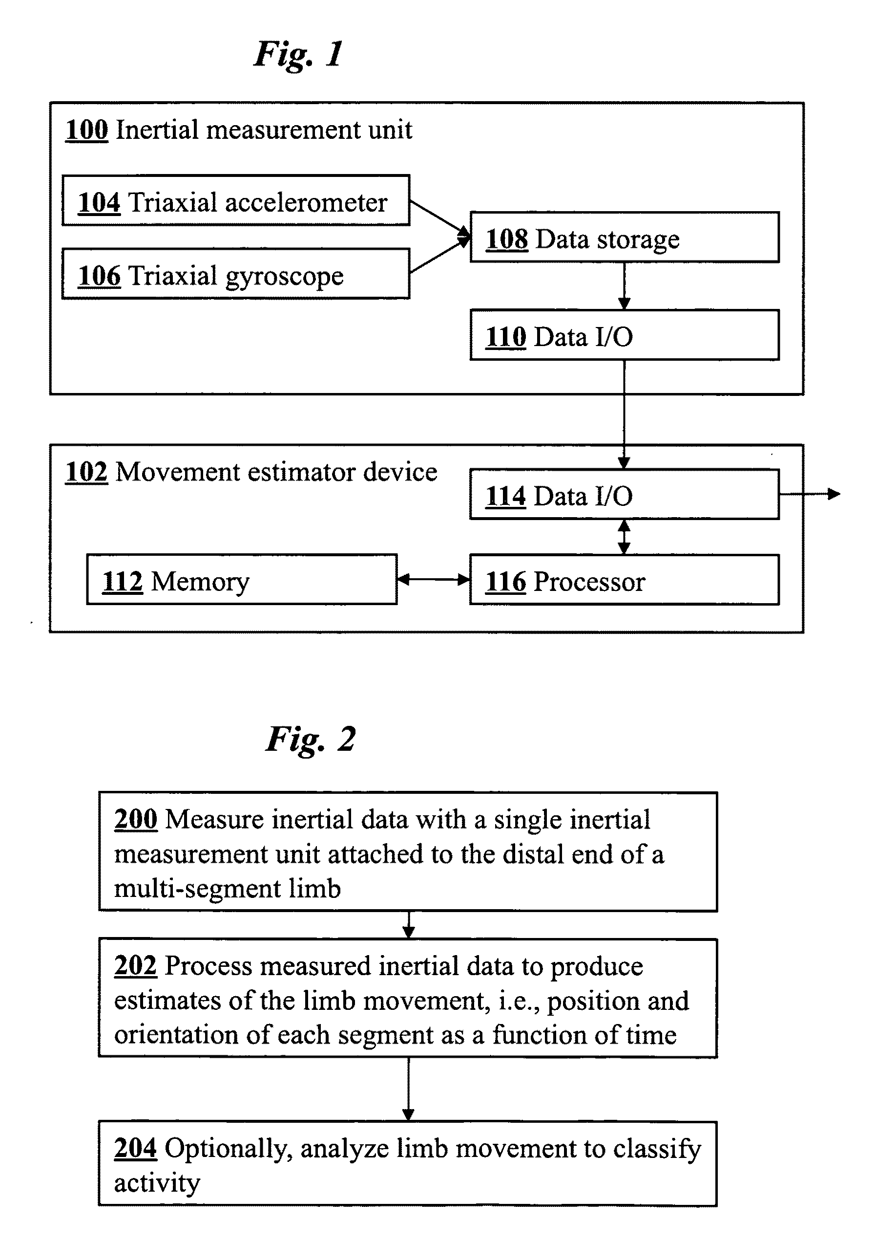
[0017]FIG. 1 is a block diagram of a system for movement estimation according to one embodiment of the invention. The system includes an inertial measurement unit 100 and a movement estimator device 102. Preferably, IMU 100 includes a triaxial accelerometer 104 and triaxial gyroscope 106. In other embodiments, IMU 100 may alternatively or additionally include magnetometers or other sensor types. The sensors 104 and 106 generate inertial data representative of the physical movement of a bodily limb. The data is stored in data storage module 108, such as flash memory. A data input / output component 110 provides an interface to communicate the stored inertial data from the IMU 100 to movement estimator 102, either in real time or off-line via a conventional wired or wireless data link.

[0018]Movement estimator 102 includes a memory 112, data input / output interface 114, and processor 116. In one embodiment, movement estimator 102 is a desktop computer. Alternatively, movement estimator 10...


PUM


Abstract

A method for estimating joint angles of a multi-segment limb from inertial sensor data accurately estimates and tracks the orientations of multiple segments of the limb as a function of time using data from a single inertial measurement unit worn at the distal end of the limb. Estimated joint angles are computed from measured inertial data as a function of time in a single step using a nonlinear state space estimator. The estimator preferably includes a tracking filter such as an unscented Kalman filter or particle filter. The nonlinear state space estimator incorporates state space evolution equations based on a kinematic model of the multi-segment limb.

Description

CROSS-REFERENCE TO RELATED APPLICATIONS[0001]This application claims priority from U.S. Provisional Patent Application No. 61 / 028,118 filed Feb. 12, 2008, which is incorporated herein by reference.FIELD OF THE INVENTION[0002]This invention relates generally to methods and devices for estimating and tracking the motion of linkages such as limbs of the human body. More specifically, it relates to improved methods for estimating the motion of a multi-segment linkage using inertial sensors.BACKGROUND[0003]The measurement and analysis of human movement has many applications including the enhancement of athletic performance, the rehabilitation from injury, and the diagnosis of neurological disorders.[0004]Bodily movements can be measured using a wide variety of techniques and types of sensors. Wearable inertial sensors—which include accelerometers and gyroscopes—enjoy the advantage that they are simple, unobtrusive, and self-contained. They are thus very suitable for continuously recordin...

Claims


Application Information

Patent Timeline
IPC IPC(8): A61B5/11
CPCA61B5/1071A61B5/1121A61B2562/0219A61B5/4528A61B5/1126
Inventor MCNAMES, JAMES NATHANEL-GOHARY, MAHMOUDPEARSON, SEAN CHRISTOPHER
Owner OREGON ACTING BY & THROUGH THE STATE BOARD OF HIGHER EDUCATION ON BEHALF OF THE PORTLAND STATE UNIV THE STATE OF
Why Eureka
Try Eureka