
Locking Bone Plates with Controlled Locking Screw Misalignment

a technology of locking screw and screw, which is applied in the field of implanted bone plate system, can solve the problems of difficulty in removing the screw afterward, and achieve the effects of less bone vascular damage, improved infection resistance, and safe and reliable removal

Inactive Publication Date: 2009-08-13
SYNTHES GMBH
View PDF6 Cites 9 Cited by
  • Summary
  • Abstract
  • Description
  • Claims
  • Application Information

AI Technical Summary

Benefits of technology

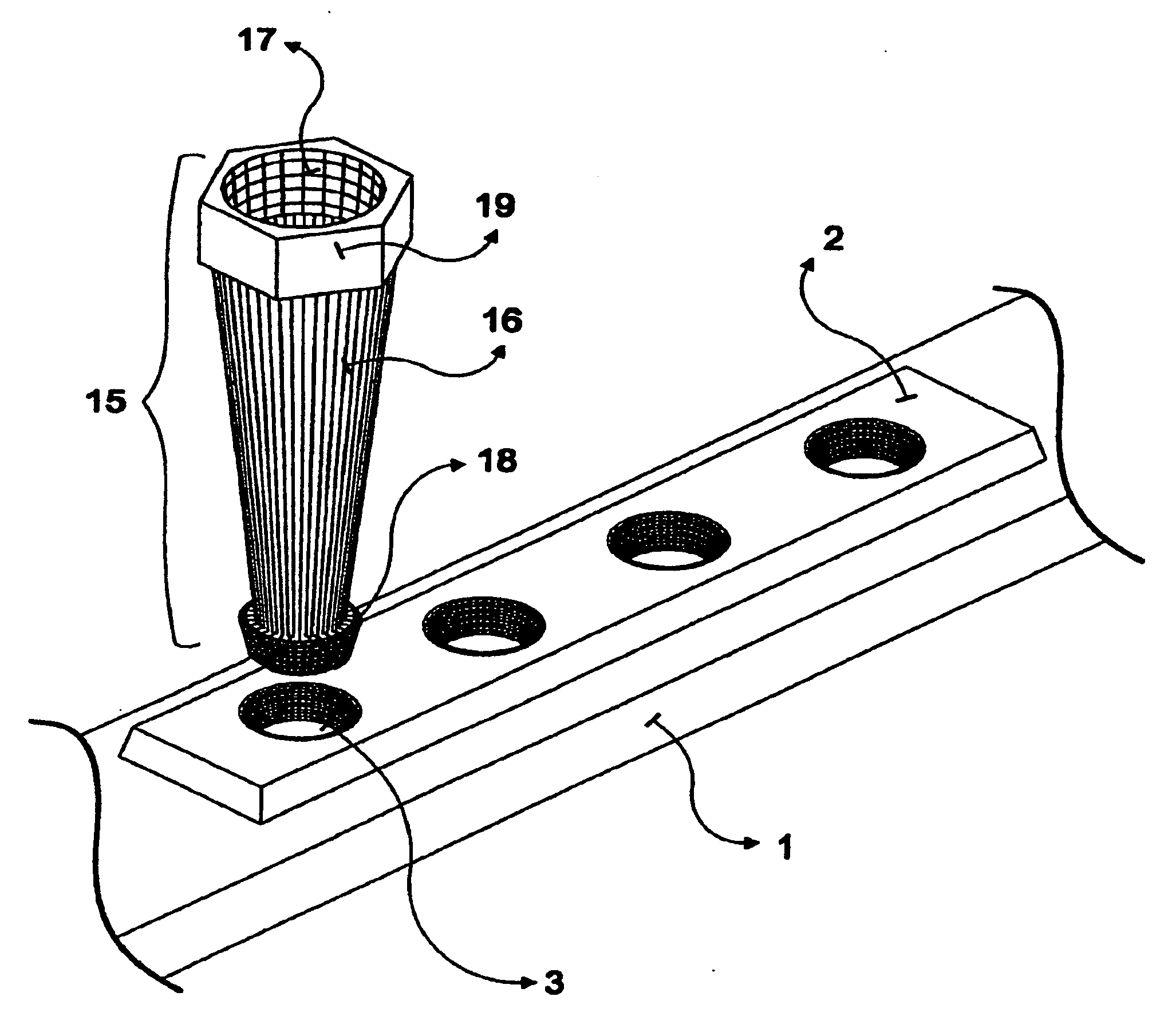
[0007]It is an object of the invention to provide a locking bone plate device and system that permits safe and reliable removal of the locking screw, should it be needed, while maintaining the advantages of locking plates, including angular stability, less bone vascular damage, and better infection resistance, among others.
[0012]A locking screw is then inserted into the drilled bone hole, the axis of the locking screw thus being slightly different than the hole axis, yet this difference is still within the tolerance required to maintain proper mechanical performance of the screw-plate coupling. This insertion technique, referred to as “controlled misalignment,” provides satisfactory mechanical performance while avoiding the jamming between the plate hole and the locking screw. This permits the surgeon to reliably and safely remove the locked screw, when necessary.

Problems solved by technology

Generally, the better the surgical technique, the more perfect the position of the locking screw with respect to the plate hole, the more stable the assembly—but, on the other hand, the more difficult it may become to remove the screw afterwards, should it be required, because of the likelihood of jamming.

Method used


Image

  • Locking Bone Plates with Controlled Locking Screw Misalignment
  • Locking Bone Plates with Controlled Locking Screw Misalignment
  • Locking Bone Plates with Controlled Locking Screw Misalignment

Examples


Embodiment Construction

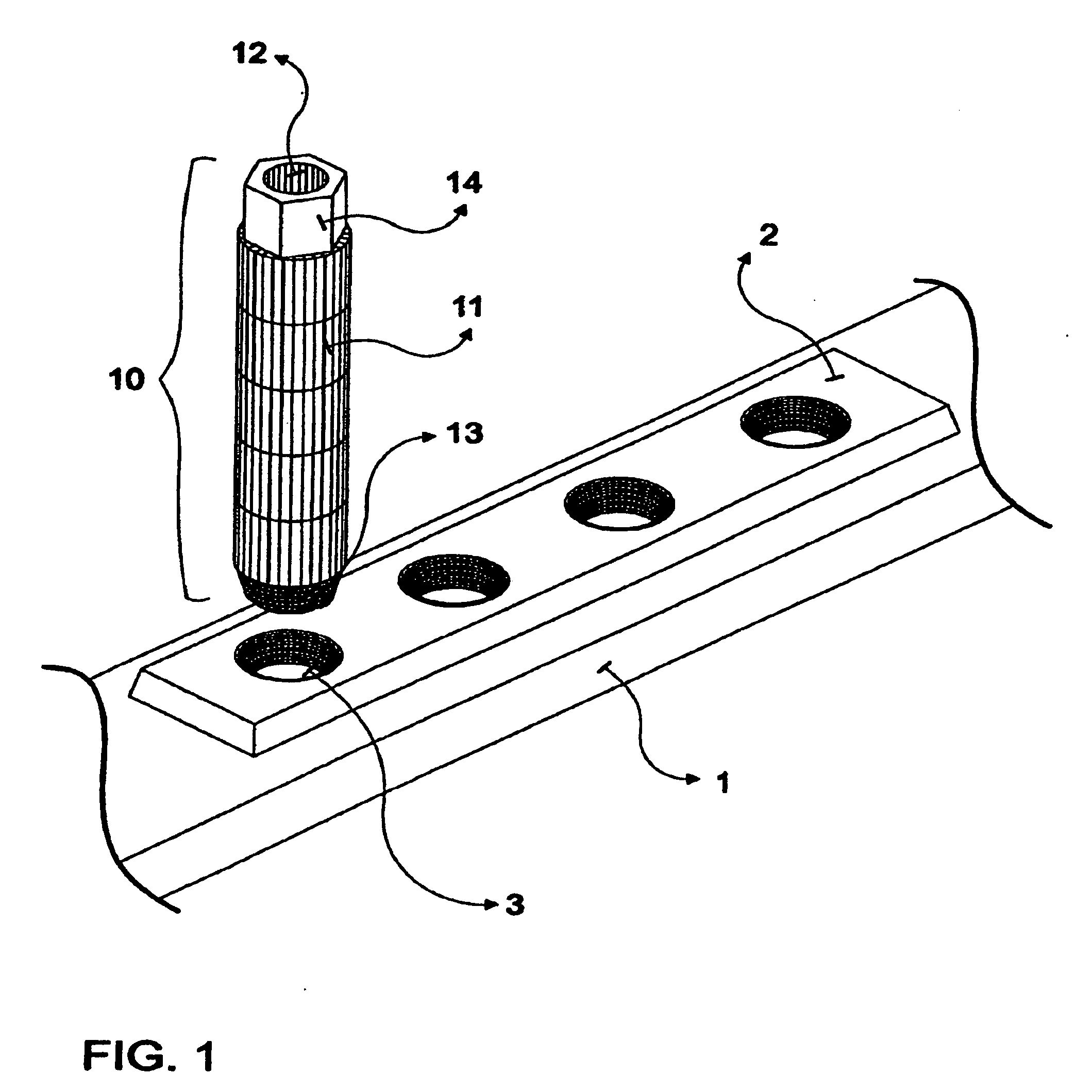
[0022]FIGS. 1-4 illustrate a conventional locking bone plate system that includes a conventional locking plate 2, a conventional cylindrical drilling sleeve 10, and a conventional locking screw 4.

[0023]Conventional bone plate 2 typically has at least two threaded holes, which in this example are conical threaded holes 3, designed to receive locking screws 4. Locking screws 4 have a threaded head 5, which in this example is conically shaped, and a threaded shaft 6 extending from head 5. The external threads on threaded head 5 mate with and preferably perfectly match the female threads in each of plate holes 3.

[0024]Conventional cylindrical sleeve 10 has a threaded head 13 that also mates with and preferably perfectly matches the female threads in each of plate holes 3.

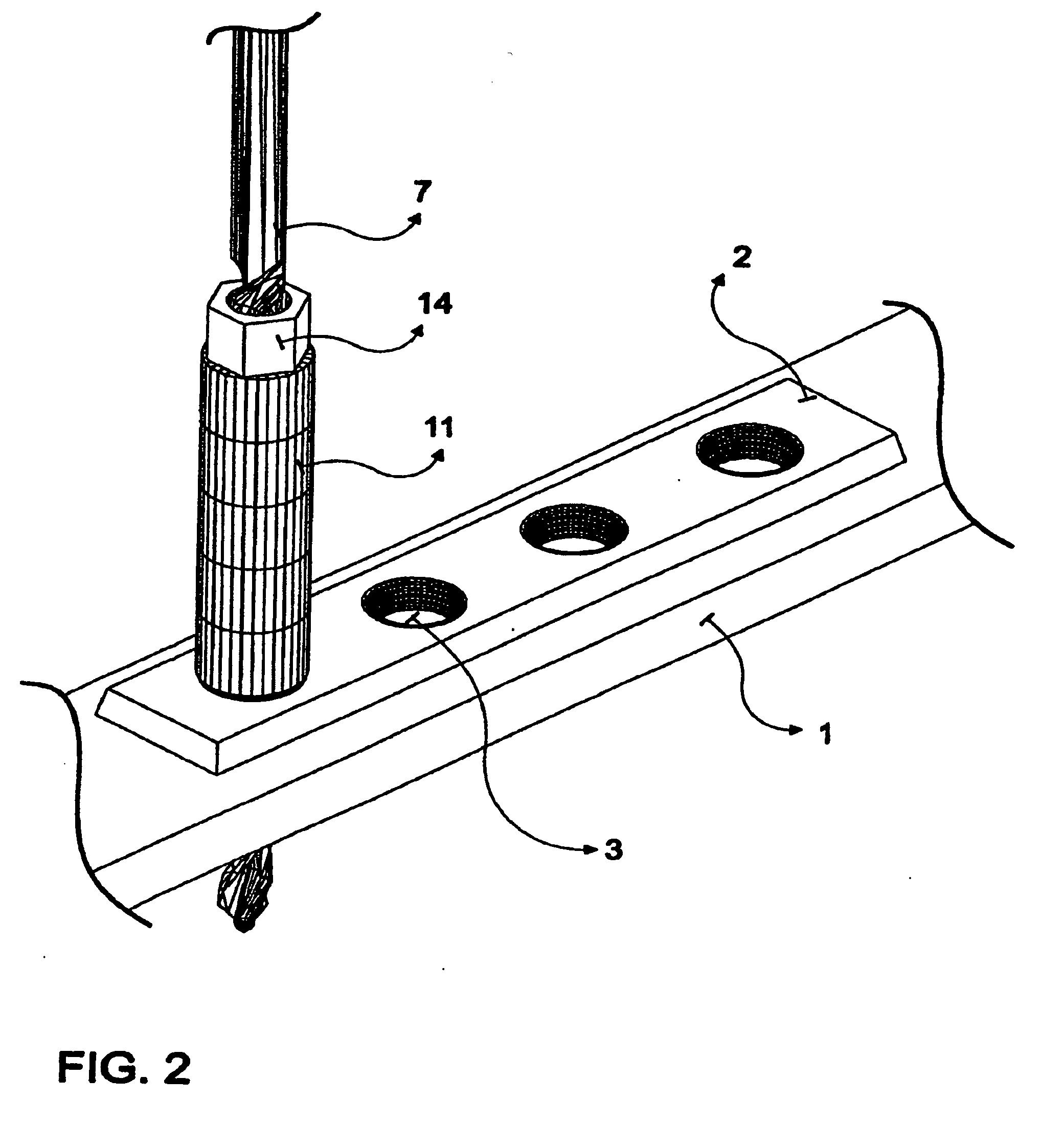
[0025]Once the conventional cylindrical sleeve 10 is properly positioned and screwed into one of plate holes 3, as shown in FIG. 2, bore 12 in cylindrical body 11 of conventional sleeve 10 is operative to guide drill bi...


PUM


Abstract

A bone plate system for fixing bone fractures includes a locking bone plate and a conically-shaped drilling sleeve. The bone plate has at least one threaded hole, and with the drilling sleeve screwed into the bone plate hole, a drill bit guided through the sleeve drills a hole into bone having a central axis angularly misaligned with the central axis of the bone plate hole. The angle between the drilled hole's central axis and the bone plate hole's central axis is equal to or less than the tolerance angle of the threads of the bone plate hole. This allows a bone plate screw to be imperfectly seated with respect to the bone plate hole and still screwed into the hole to lock the plate without jamming the screw head into the plate hole, while still allowing the screw to be screwed out if needed.

Description

FIELD OF THE INVENTION[0001]The invention relates generally to implanted bone plate systems for fixing bone fractures. More particularly, the invention relates to locking bone plates with locking screws that are intentionally and controllably misaligned angularly through holes in the bone plate.BACKGROUND OF THE INVENTION[0002]Since the early 20th century, bone plates and screws have been used for internal fixation of broken bones. As of the late 1980's, locking bone plates were developed. A locked bone plate uses a locking screw that has threads on an outer surface of its head that mates with corresponding threads in the bone plate hole. Because of the fixed relationship between locking screws and the bone plate, locking screws provide high resistance to shear or torsional forces. Thus, the main feature of such “locking bone plates” is a solid fixation between the plate and inserted screws. The advantages of locked plates—angular stability, less bone vascular damage, better infecti...

Claims


Application Information

Patent Timeline
Patent Type & Authority Applications(United States)
IPC IPC(8): A61B17/80A61B17/58
CPCA61B17/8057A61B17/1728A61B17/17A61B17/84A61B17/86A61B17/88
Inventor FERNANDEZ DELL'OCA, ALBERTO A.
Owner SYNTHES GMBH
Learn More