Catheter Device

a catheter and catheter technology, applied in the field of catheter devices, can solve the problems of stent release, failure of the device, patient risk, in use, etc., and achieve the effects of convenient bending, convenient atraumatic withdrawal of the catheter system, and simplified bonding task

Active Publication Date: 2009-08-13
ANGIOMED GMBH & CO MEDIZINTECHNIK KG
View PDF16 Cites 44 Cited by
  • Summary
  • Abstract
  • Description
  • Claims
  • Application Information

AI Technical Summary

Benefits of technology

[0024]The proximal end of the sheath can be joined to a metal collar that defines a proximal guidewire exit port lumen and another lumen to slidably receive the outer tube of the catheter shaft. The collar can be given a domed shape facing proximally, to facilitate atraumatic withdrawal of the catheter system.
[0025]One way of connecting the shaft tube to the stopper is by way of a pusher-guider tube which defines a guidewire lumen and carries the stopper at a location near the distal end of the pusher-guider tube, or at its distal end. The proximal end of the pusher-guider tube is arranged to one side of the distal end of the shaft tube and fixed relative to it, such as by welding or glueing. Conveniently, both the pusher-guider tube and the shaft tube are of metal such as stainless steel, simplifying the task of bonding together side-by-side the proximal end of the pusher tube and the distal end of the shaft tube, as by welding or brazing. Other means of joining these tube sections will be apparent to those readers skilled in the field, who will also appreciate that adhesive compositions are generally disfavoured, whenever failure of the adhesive bond results in failure of the device and risk to the patient, in use.
[0026]Distal of the stopper, the pusher-guider tube is not required to carry any substantial axial compressive stress. In any event, it should be soft and easily bendable so as to keep the catheter tip as floppy as possible. The compression resistant pusher-guider tube could be extended distally beyond the stopper, all the way to the distal end of the sheath, in order to define a guidewire lumen which extends within the pusher tube all the way to the distal end of the system. Indeed, the pusher tube could extend into an atraumatic tip distal of the distal end of the sheath. In this way, the tapered tip of the sheath could be omitted.
[0027]Thus, there can be provided, distal of the stopper, a pusher tube extension, which continues the guidewire lumen from the stopper to the distal end of the system, but which may be of less heavy construction, being formed for example of thin wall polymer tube. Another useful purpose of such a guidewire lumen distal of the stopper is for carrying a radiopaque marker band to indicate the distal end of the stent within the delivery system, so that the radiologist can determine with precision where the stent in the delivery system is located relative to the target stenting site.

Problems solved by technology

One disadvantage noted by the present inventor is that release of the stent requires the medical practitioner to maintain the inner pusher shaft unchanged in axial disposition relative to the site of stenting in the body of the patient, while pulling back on the outer tube of the shaft to release the stent.
Any friction or resistance to axial movement of the outer tube in the lumen in which it is located hinders the objective of maintaining the stopper in a precise disposition relative to the target stenting site.
If the pulling system stretches, then a step-wise movement can have the consequence of a time-dependent response at the distal end of the system, and a relaxation of the pulling system between successive pulling steps, with consequent undesirable reverse distal movement of the sheath or else “lost movement” in the pulling system as it once again strains to take up the pull tension with successive step-wise pulls at the proximal end of the system.
Other means of joining these tube sections will be apparent to those readers skilled in the field, who will also appreciate that adhesive compositions are generally disfavoured, whenever failure of the adhesive bond results in failure of the device and risk to the patient, in use.

Method used


Image

  • Catheter Device
  • Catheter Device
  • Catheter Device

Examples


Embodiment Construction

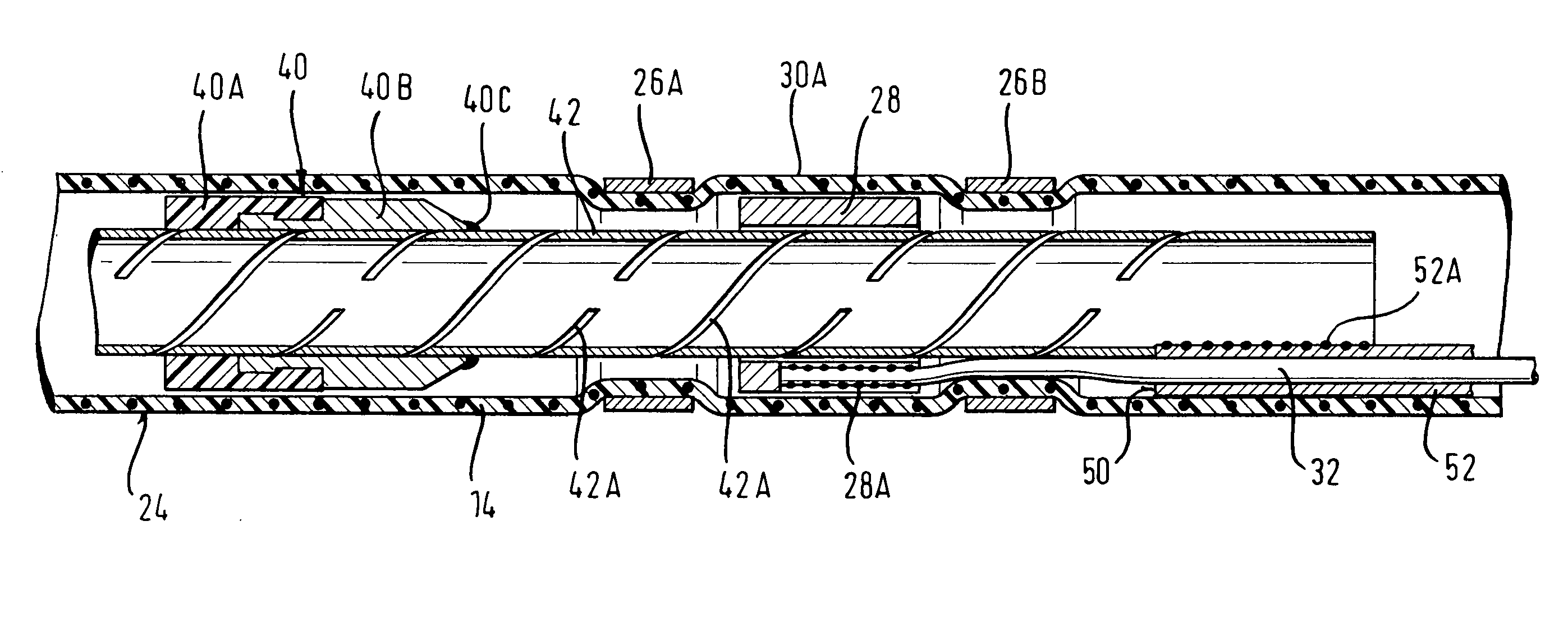
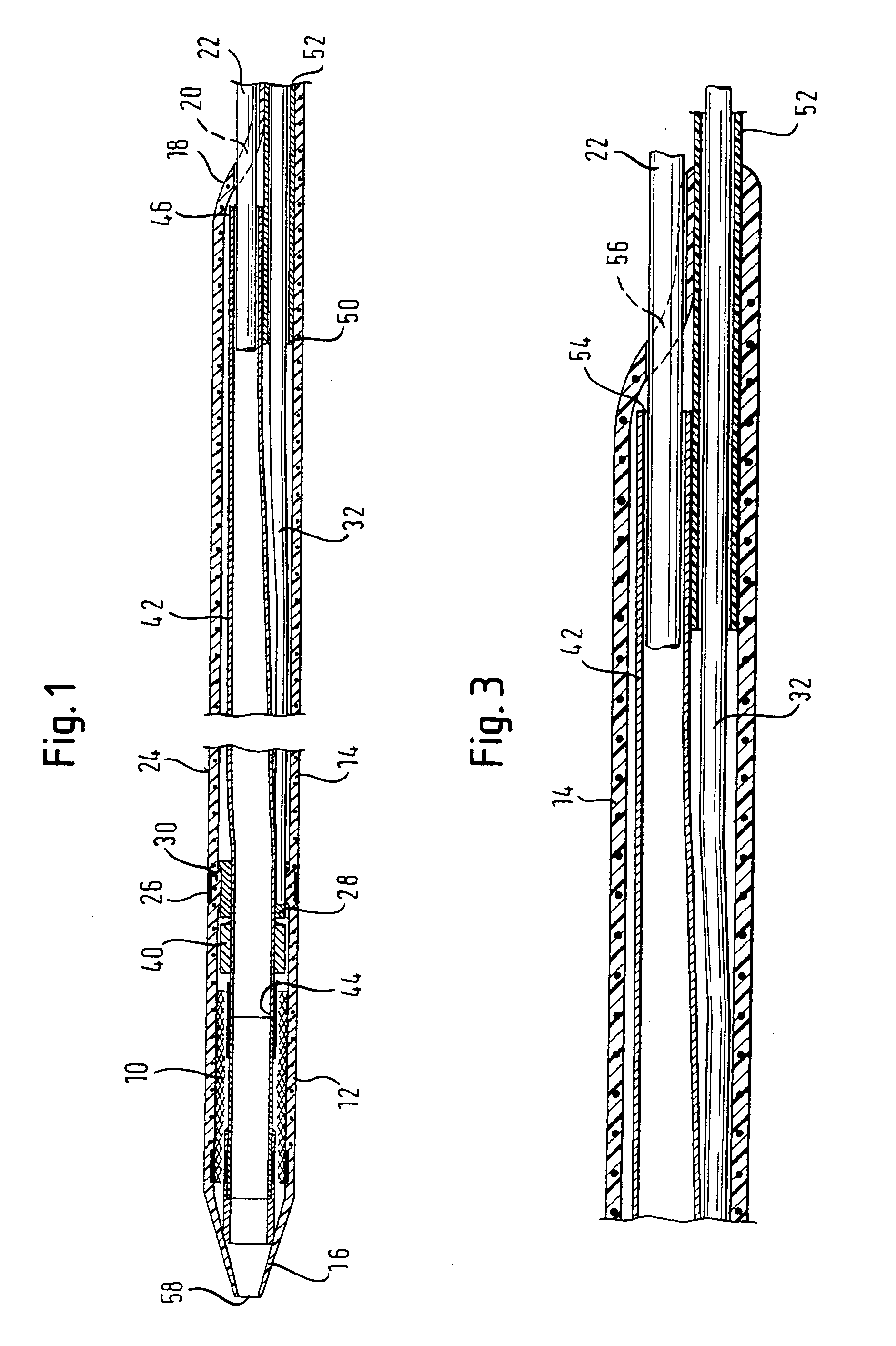
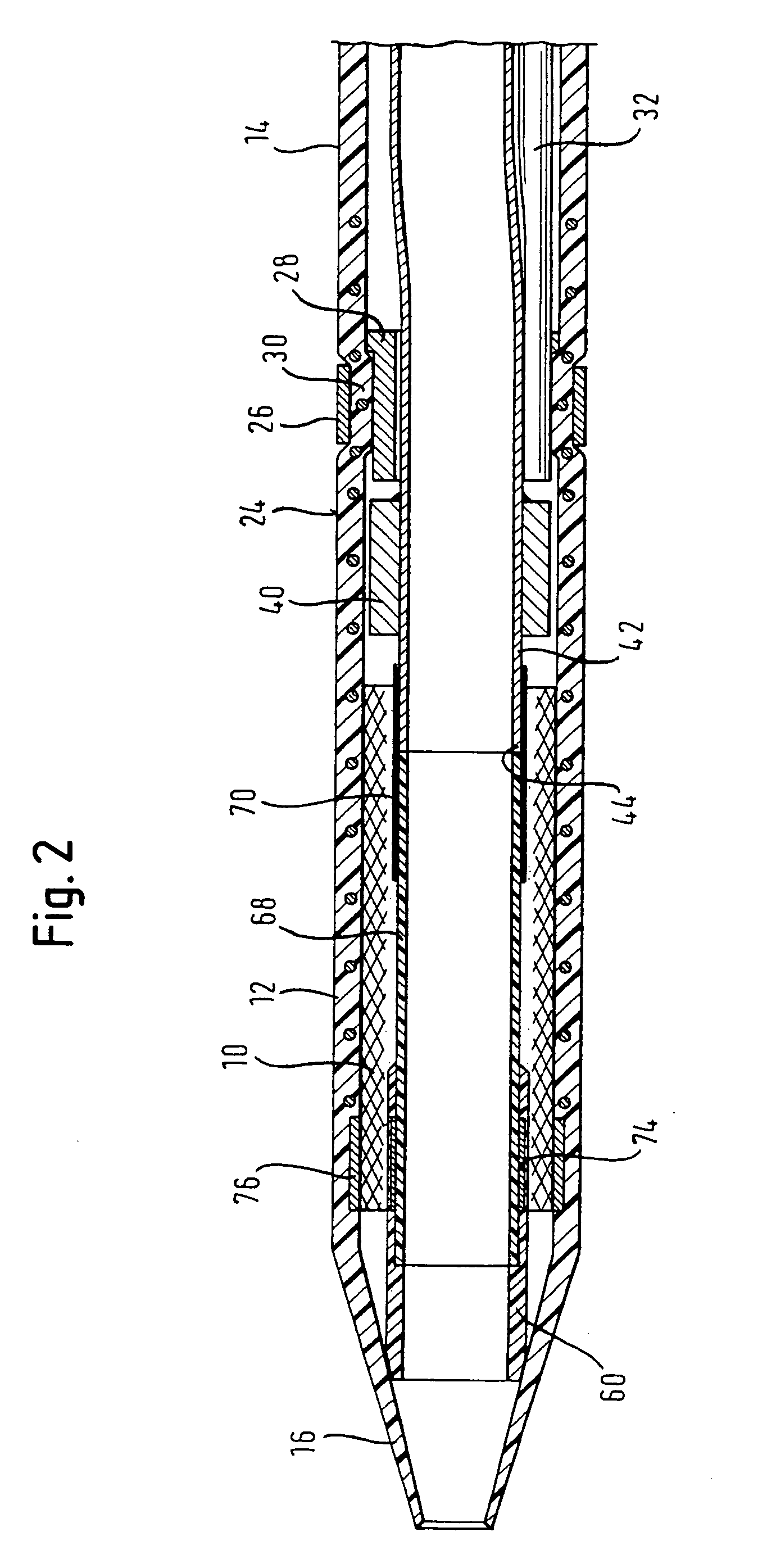
[0047]Referring to FIGS. 1, 2 and 3 which form part of the invention described in WO-A-2005 / 053574, a self-expanding stent 10, or stent graft, lies inside the distal end zone 12 of a sheath 14 with a tapered distal tip 16 and a heat-formed proximal end 18 which defines the orifice 20 of a proximal guidewire exit port for a guidewire 22. Being a self-expander, the stent 10 is, at least at body temperature, putting compressive stress on the luminal surface of the sleeve 14 in the distal end zone 12. Proximal of the stent 10, and on the abluminal surface 24 of the sleeve 14, is a swaged marker band 26 of radiopaque metallic material, which is pressing radially inwardly the material of the sheath 14 within the band 26. Radially inside the sheath at this point is a stepped metal annulus 28 which is itself put under radially inwardly compressive stress by the material 30 of the sheath 14 inside the marker band 26. Thus, the sheath material 30 is compressed between metal bands inside (28) ...


PUM


Abstract

A catheter device having a shaft that extends from a proximal end to a distal end to carry on its distal end a self-expanding implant for intraluminal advance on a guidewire and delivery of the implant to an implant site by proximal withdrawal of a longitudinal sheath that lies radially outside the implant in the catheter, the catheter including a first shaft element to pull the sheath proximally and a second shaft element to push the implant distally to prevent the implant moving proximally with the sheath when the sheath is pulled proximally, wherein the sheath is freely rotatable with respect to the first shaft element during the said intraluminal advance and, during proximal movement, is caused to abut the first shaft element at an abutment position by a reduced inner diameter portion of the sheath proximal of the abutment position.

Description

BACKGROUND OF THE INVENTION[0001]1. Field of the Invention[0002]This invention relates to a catheter device having a shaft, a rapid-exchange guidewire lumen (one which terminates at a proximal guidewire exit port that is distal of the proximal end of the catheter) and a distal end which exhibits a sheath which can be withdrawn proximally to release a self-expanding implant such as a stent. To prevent the self-expanding stent moving proximally with the proximally-moving sheath, the catheter device includes a stopper which bears on the stent and resists its proximal movement.[0003]2. Background Prior Art[0004]Conventionally, such a catheter device exhibits a shaft comprising an outer tube connected to the sheath and an inner shaft connected to the stopper, whereby the proximal movement of the sheath is accomplished by imposing an endwise tension on the outer tube, with the inner shaft carrying an endwise compression stress, as the stopper at the distal end of the inner shaft works to ...

Claims


Application Information

Patent Timeline
Patent Type & Authority Applications(United States)
IPC IPC(8): A61F2/84A61F2/95A61F2/966
CPCA61F2/95A61F2/966A61M2025/0175A61F2002/9665A61M2025/0004A61F2002/9517A61F2/9517
Inventor DORN, JURGENWUEBBELING, MARTINELSASSER, ERHARD
Owner ANGIOMED GMBH & CO MEDIZINTECHNIK KG
Why Eureka
Try Eureka