Cyclonic liquid degassing separator and method for degassing a fluid mixture

a technology of liquid degassing separator and separator, which is applied in the direction of liquid degasification, separation process, reverse direction vortex, etc., can solve the problems of reducing the separation performance of the device, large equipment pieces, and limited separation efficiency,

Active Publication Date: 2009-08-20
SHELL OIL CO
View PDF7 Cites 25 Cited by
  • Summary
  • Abstract
  • Description
  • Claims
  • Application Information

AI Technical Summary

Benefits of technology

[0012]the fluid mixture is accelerated in a throat section of a vortex tube such that the static pressure of the fluid mixture is decreased and vaporizable components evaporate into a gaseous phase;
[0017]An advantage of homogenizing the gas-liquid mixture is that the speed of sound in such a homogenized mixture is lower than in an inhomogeneous mixture. The speed of sound in a substantially homogeneous gas-liquid mixture may be less than 300 m / s.
[0020]Furthermore a substantially inert gas may be injected into the gas-liquid mixture to enhance homogenization of the gas-liquid mixture.
[0031]a vortex tube having a throat section in which the fluid mixture is accelerated such that the static pressure of the fluid mixture is decreased and vaporizable components evaporate into a gaseous phase;

Problems solved by technology

A disadvantage of the latter group of known cyclonic separators is that they generally are large pieces of equipment and have a limited separation efficiency.
A disadvantage of the known method is that the swirling motion induced by the helical grooves (24) induces dehomogenisation of the fluid mixture by centrifugal forces.
Such dehomogenisation before the nozzle reduces the separation performance of the device.

Method used


Image

  • Cyclonic liquid degassing separator and method for degassing a fluid mixture
  • Cyclonic liquid degassing separator and method for degassing a fluid mixture
  • Cyclonic liquid degassing separator and method for degassing a fluid mixture

Examples


Embodiment Construction

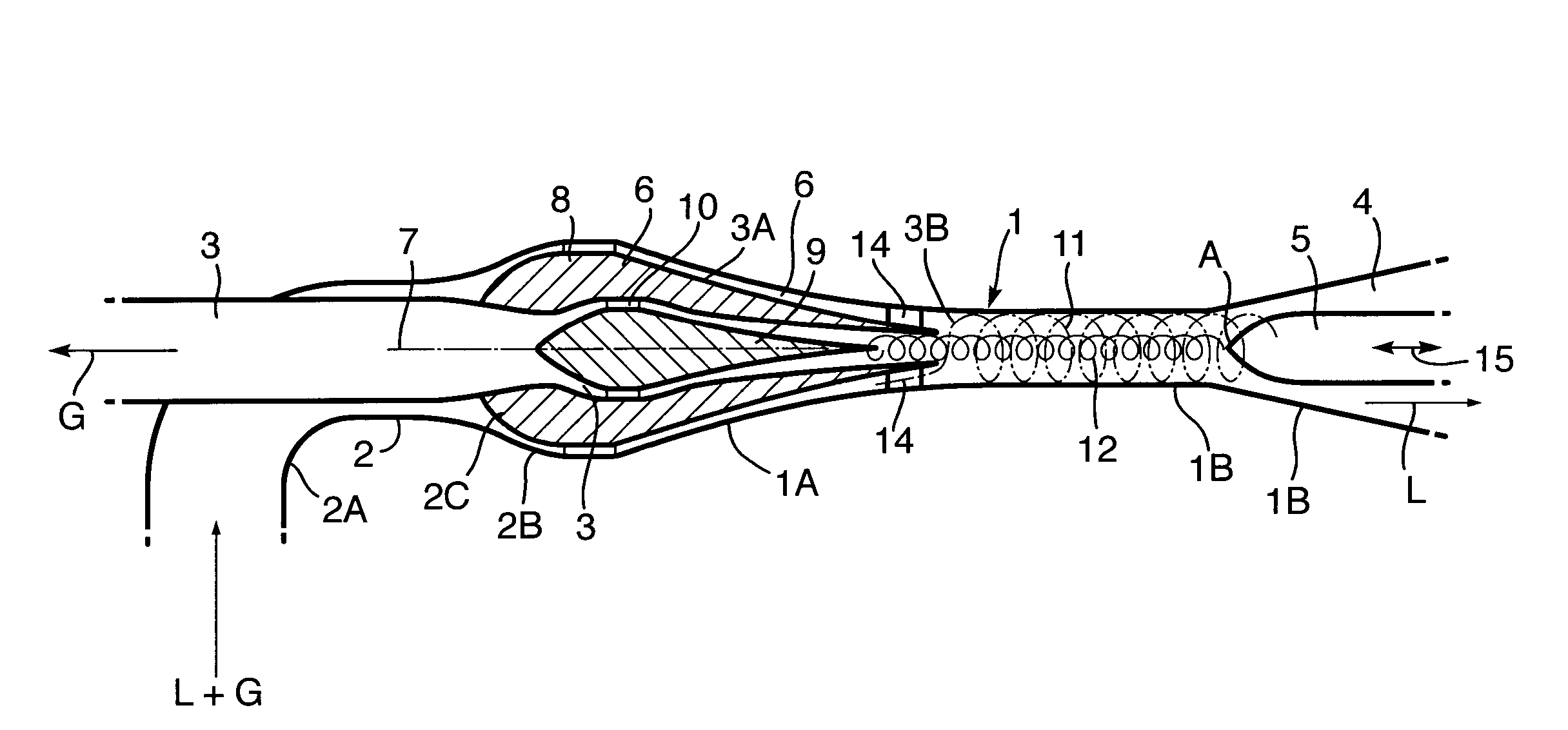
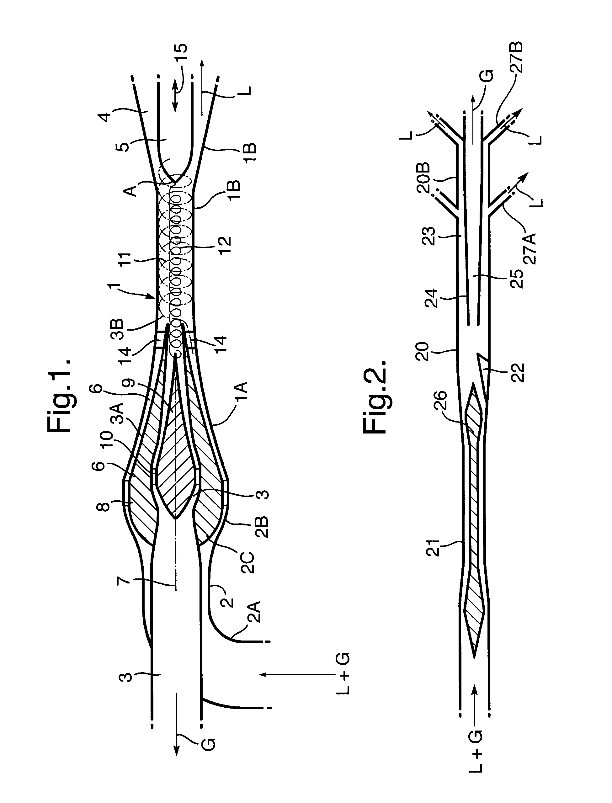
[0046]FIG. 1 depicts a cyclonic liquid degassing separator, which comprises a vortex tube 1, an untreated fluid inlet conduit 2, a gas outlet conduit 3 and a degassed liquid outlet conduit 4.

[0047]The vortex tube 1 has a trumpet-shaped proximal end 1A and a diverging distal end 1B.

[0048]The liquid outlet conduit 4 is formed by an annular space between the inner surface of the diverging distal end 1B of the vortex tube 1 and a bullet-shaped deflection body 5.

[0049]The trumpet-shaped proximal end 1A of the vortex tube 1 is connected to the diverging outer wall 2B of the fluid inlet conduit 2.

[0050]A series of flow straightening vanes 8 is arranged in the diverging annular end-section 2C of the inlet conduit 2B, which vanes 8 induce the untreated fluid mixture to flow in a substantial axial direction relative to a central axis 7 of the separator, which vanes 8 inhibit swirling of the fluid mixture relative to the central axis 7 in an annular throat section 6 formed between the inner su...


PUM

PropertyMeasurementUnit
speedaaaaaaaaaa
sound velocityaaaaaaaaaa

Abstract

A method and cyclonic separator are disclosed for degassing a fluid mixture comprising a carrier liquid and gaseous and / or vaporizable components, wherein: the fluid mixture is accelerated in a throat section (6, 21) of a vortex tube (1, 20) such that the static pressure of the fluid mixture is decreased and vaporizable components evaporate into a gaseous phase and the fluid mixture flows as a substantially homogeneously dispersed gas-liquid mixture through the throat section; the accelerated fluid mixture is induced to swirl within a tubular mid section of the vortex tube such that the fluid mixture is separated by centrifugal forces into a degassed liquid fraction and a gas enriched fraction; the degassed liquid fraction is induced to flow into a annular liquid outlet conduit (4, 21); and the gas enriched fraction is induced to flow into a central gas outlet conduit (3, 24). An advantage of inducing the fluid mixture to flow as a substantially homogeneously dispersed gas-liquid mixture through the throat section is that the velocity of sound in such a mixture is low, thereby increasing the Mach number and the pressure reduction in the throat section and enhancing evaporation of gas bubbles in the mixture.

Description

BACKGROUND OF THE INVENTION[0001]The invention relates to a cyclonic separator and method for degassing a fluid mixture.[0002]U.S. Pat. No. 6,402,799 discloses a cyclonic separator in which a gas-liquid mixture is injected via a tangential inlet into a horizontal vortex tube in which the gaseous and liquid fractions are at least partly separated and the liquid fraction forms a film alongside the inner wall of the vortex tube and is discharged via a radial outlet, whereas the gaseous fraction is concentrated near the central axis of the vortex tube and discharged via a central outlet.[0003]International patent applications WO9901194 and WO03029739 disclose cyclonic separators wherein a gas stream is accelerated in a vortex tube to a near sonic or supersonic velocity and thereby expanded and adiabatically cooled such that liquid or solid particles are formed which are discharged via an outlet at the outer circumference of the tube, whereas a dry gas fraction is discharged via a centra...

Claims


Application Information

Patent Timeline
Patent Type & Authority Applications(United States)
IPC IPC(8): B01D19/00B04C3/00B04C3/06
CPCB01D17/0217B04C3/00B04C3/06B04C5/181B04C5/103B04C5/13B04C5/16B04C5/06
Inventor BETTING, MARCOPRAST, BARTVAN SANTEN, HELMARSCHELLEKENS, CORNELIUS JOHANNESVERBEEK, PAULUS HENRICUS JOANNESWILKINSON, PETER MERVYN
Owner SHELL OIL CO
Why Eureka
Try Eureka