Electronic device having piezoelectric pump

Inactive Publication Date: 2009-08-20
SONY CORP
View PDF13 Cites 17 Cited by
  • Summary
  • Abstract
  • Description
  • Claims
  • Application Information

AI Technical Summary

Benefits of technology

[0020]By the present invention, it is possible to prevent or reduce deterioration of a

Problems solved by technology

However, in the case of an air-cooling fan, the pressure that can be generated at the time of making a wind is low, and thus it has been necessary to keep an air-flowing path large in or

Method used


Image

  • Electronic device having piezoelectric pump
  • Electronic device having piezoelectric pump
  • Electronic device having piezoelectric pump

Examples


Embodiment Construction

[0034]In the following, a description will be given of an embodiment of the present invention with reference to the drawings.

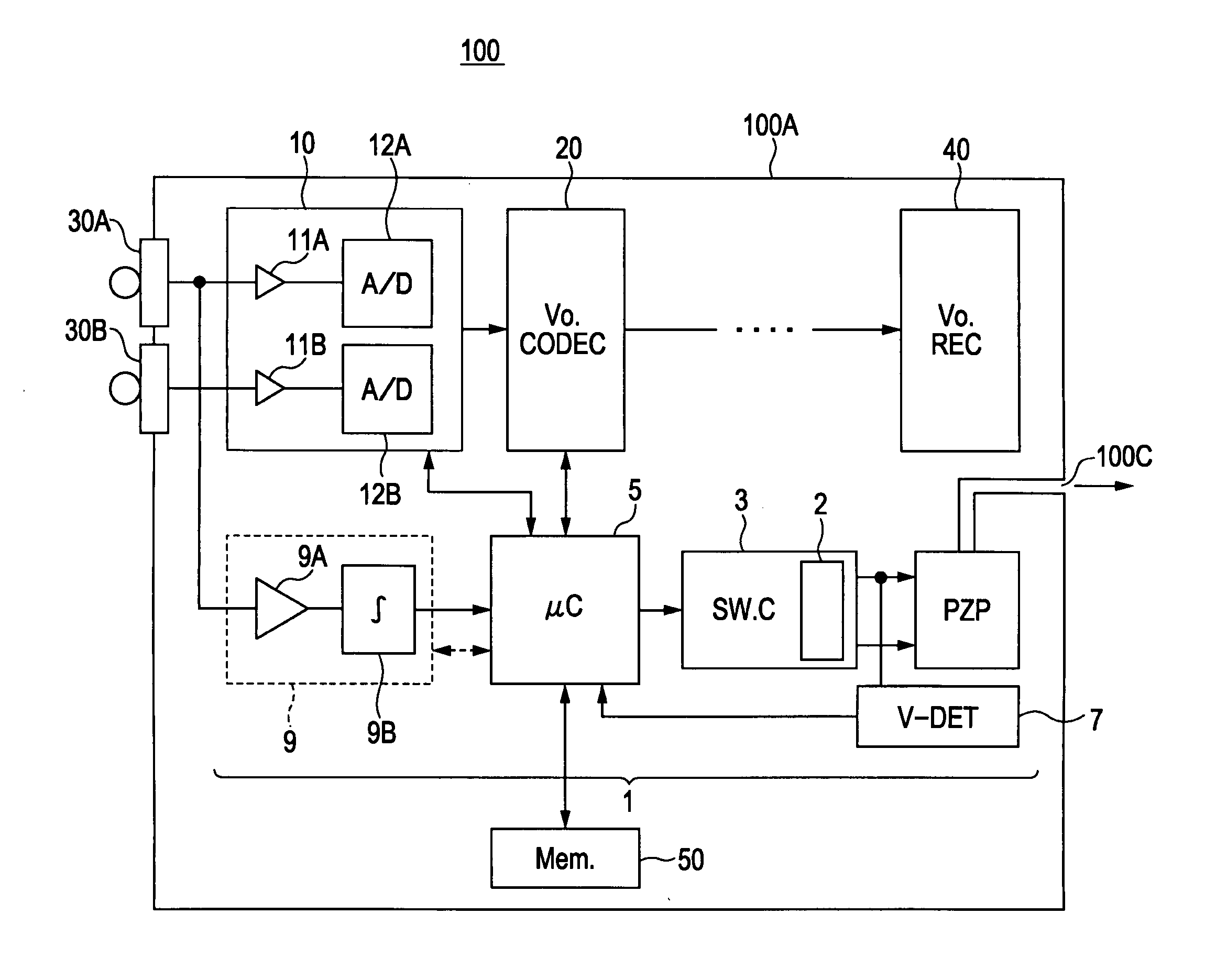
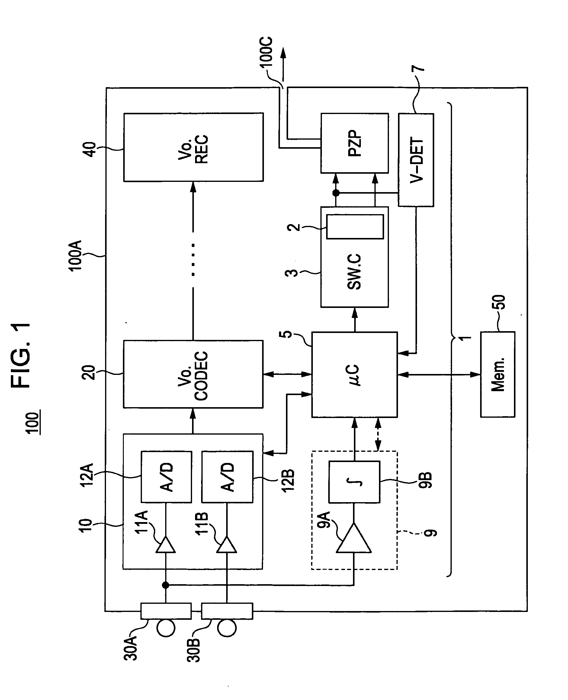
[0035]An electronic device according to the present embodiment uses a piezoelectric (air) pump utilizing a piezoelectric element as an air-cooling device, and at least can receive and record audio input from the outside.

[0036]The piezoelectric (air) pump is useful for a system serving as a countermeasure against an increase in the internal temperature of a mobile device and a stationary device. In particular, in the case of a mobile device, a case of the device is small in size, and thus a fan-type air cooling apparatus used so far is sometimes difficult to be disposed.

[0037]The piezoelectric pump has a feature enabling such a high air discharge pressure that is difficult for an air-cooling fan method to obtain while the pump is small in size. Thus, piezoelectric pump is particularly useful for a system serving as a countermeasure against an increase in the in...


PUM


Abstract

An electronic device having a piezoelectric pump. The electronic device includes: an audio input section; an audio recording section recording input sound from the audio input section; a piezoelectric pump cooling air by a piezoelectric element; a drive circuit driving the piezoelectric element; and a control circuit monitoring and controlling operation of the audio input section, the audio recording section, and the drive circuit, wherein when an operation mode being monitored is an audio recording mode, in which the input sound is used for recording by the audio recording section, the control circuit controls the drive circuit to decrease the amount of air flow exhausted outside from the piezoelectric pump, and when the operation mode being monitored is another mode without audio recording, the control circuit maintains the amount of the air flow.

Description

CROSS REFERENCES TO RELATED APPLICATIONS[0001]The present invention contains subject matter related to Japanese Patent Application JP 2008-036410 filed in the Japanese Patent Office on Feb. 18, 2008, the entire contents of which are incorporated herein by reference.BACKGROUND OF THE INVENTION[0002]1. Field of the Invention[0003]The present invention relates to an electronic device having a piezoelectric pump which lowers the internal temperature of the device by moving air through vibration of a piezoelectric element.[0004]2. Description of the Related Art[0005]A drive circuit of a piezoelectric element has come into practical use for a liquid spray and various kinds of actuators (for example, Japanese Patent Nos. 2618685 and 3115618).[0006]In this drive circuit, a switching transistor is connected to a primary winding of a transformer, and a piezoelectric element is connected to a secondary winding of the transformer. The circuit generates and controls a drive voltage of the piezoe...

Claims


Application Information

Patent Timeline
IPC IPC(8): H02N2/06
CPCF04B43/046H01L41/042H01L2924/0002H01L2924/00H10N30/802
Inventor OSANO, KEIJI
Owner SONY CORP
Why Eureka
Try Eureka