Rotation-angle-detecting apparatus, rotating machine, and rotation-angle-detecting method

a technology of rotating machines and detecting apparatus, which is applied in the direction of magnetic measurements, instruments, measurement devices, etc., can solve the problems of reducing the accuracy of the rotation angle, the inability to detect the rotation angle with high accuracy, and the drastic decrease of the element. achieve the effect of higher accuracy

Active Publication Date: 2009-08-20
HITACHI METALS LTD
View PDF2 Cites 200 Cited by
  • Summary
  • Abstract
  • Description
  • Claims
  • Application Information

AI Technical Summary

Benefits of technology

[0024]The rotation period of the magnetization direction of the free layer is 1 / N times (N is an integer of 2 or more) of the rotation period of the magnet rotor, resulting in high resolution. The rotation-angle-detecting apparatus is preferably mounted to a rotating machine.
[0035]The term “near the magnet rotor” means that the distance between the magnet rotor and the sensor device is set to meet the condition that a free layer in the spin-valve, giant-magnetoresistive device rotates when the magnet rotor is rotated. Because elements are arranged with inclination of 90° in sensor bridges in one sensor device, the rotation angle can be measured accurately even if the sensor devices are not positioned with phase difference of 90°.
[0037]The term “arctangent calculation” means to determine the value of θ meeting the relation of tan θ=y / x from the first sinusoidal output signal x and the second sinusoidal output signal y. To improve rotation angle detection accuracy, the rotation-angle-detecting apparatus preferably comprises a means for inverting at least one of signals output from the first and second sensor devices before treatment. The inversion of three signals is included as equivalence to the inversion of one signal.
[0100]In the rotation-angle-detecting apparatus comprising a rotatably supported magnet rotor, a both-end-supported-type magnet rotor suffers less rotation axis deviation, resulting in rotation angle detection with higher accuracy, than a cantilever-type magnet rotor (having a rotation shaft extending therefrom only on one side) does. Further, the both-end-supported-type magnet rotor makes the detection apparatus smaller.

Problems solved by technology

However, because the output of a Hall element drastically decreases when the distance between the Hall element and a rotating magnet surface (spacing) increases, the Hall element is so vulnerable to spacing variation that it cannot easily detect the rotation angle with high accuracy.
Further, because ambient temperature change leads to large variation of output due to the change of magnet characteristics (change of magnetic flux), it cannot detect the rotation angle stably.
To detect the change of the magnetic flux direction, the amplitudes of pluralities of varied outputs should be corrected by an external circuit, resulting in a complicated structure.
This method is a signal-treating method adjusting output amplitudes by a circuit, but this reference fails to disclose a method of suppressing the deformation of the output.
However, the rotation-angle-detecting apparatus of JU 62-076607 A is large and complicated because it needs a signal generator for applying SW and CW to the ferromagnetic sensors.
Accordingly, there is unevenness depending on an angle between a magnetization direction and an anisotropy direction when the magnetization rotates, failing to achieve smooth rotation.
Thus, an output waveform is deformed, making it difficult to detect the rotation angle accurately.
Accordingly, this technology cannot be applied to a both-end-support structure having a shaft penetrating a magnet.
Also, because the rotation of the magnet is easily deviated, it is difficult to detect the rotation angle accurately.
As shown in FIG. 3 of JP 2006-010346 A, however, the deviation of the magnetoresistive device in a direction shown by the arrow L from the center axis of the magnet due to errors in assembling and machining increases the angle error of an output, resulting in difficulty in the accurate detection of the rotation angle.
When the magnet rotor generates a large magnetic field, the output of the magnetic sensor is inverted, resulting in large deformation of the output.
Also, when the ratio Bsig / Bbias of the magnetic field (Bsig) of the magnet rotor to the magnetic field (Bbias) of the bias magnet exceeds 0.7, a sinusoidal output cannot easily be obtained, resulting in a deformed output.
With such tendency, the positional deviation of the magnet rotor in a rotation axis direction provides the output with amplitude variations and deformation, making it difficult to detect the rotation angle with high accuracy.
In addition, the existence of the bias magnet makes it difficult to miniaturize the sensor device.
When the bias magnet is used, the laminated giant-magnetoresistive device has the same problem as that of the MR element as described above.
However, as is clear from FIG. 2 in JP 61-142782 A, a signal representing a resistance change ratio cannot be obtained in a certain angle range near a center between an N pole and an S pole, so that it cannot be used as an absolute angle sensor.
However, when a magnetosensitive surface of a Hall element as one sensor is at a space position, a notch of the other sensor is at that space position, resulting in deviation.
Having the yoke and the coils, however, the resolver is large, heavy and expensive with complicated winding.
Accordingly, demand is mounting for small, lightweight sensors capable of detecting the rotation angle with high accuracy, but the above conventional apparatuses are not sufficiently accurate.

Method used


Image

  • Rotation-angle-detecting apparatus, rotating machine, and rotation-angle-detecting method
  • Rotation-angle-detecting apparatus, rotating machine, and rotation-angle-detecting method
  • Rotation-angle-detecting apparatus, rotating machine, and rotation-angle-detecting method

Examples


example 1

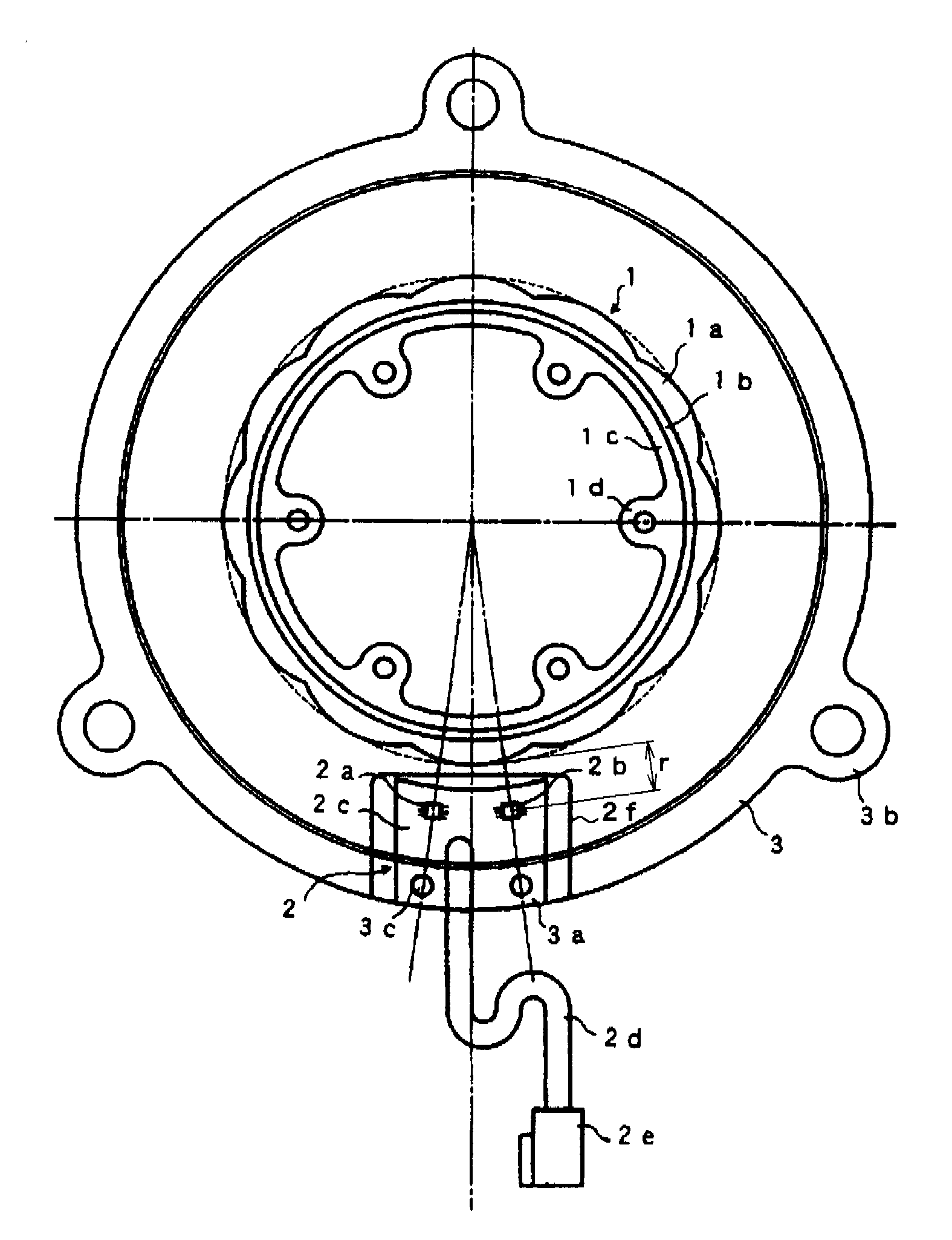
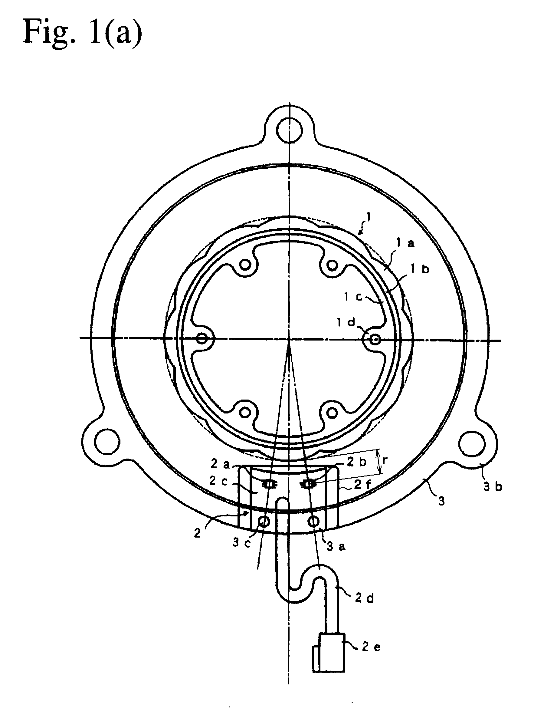
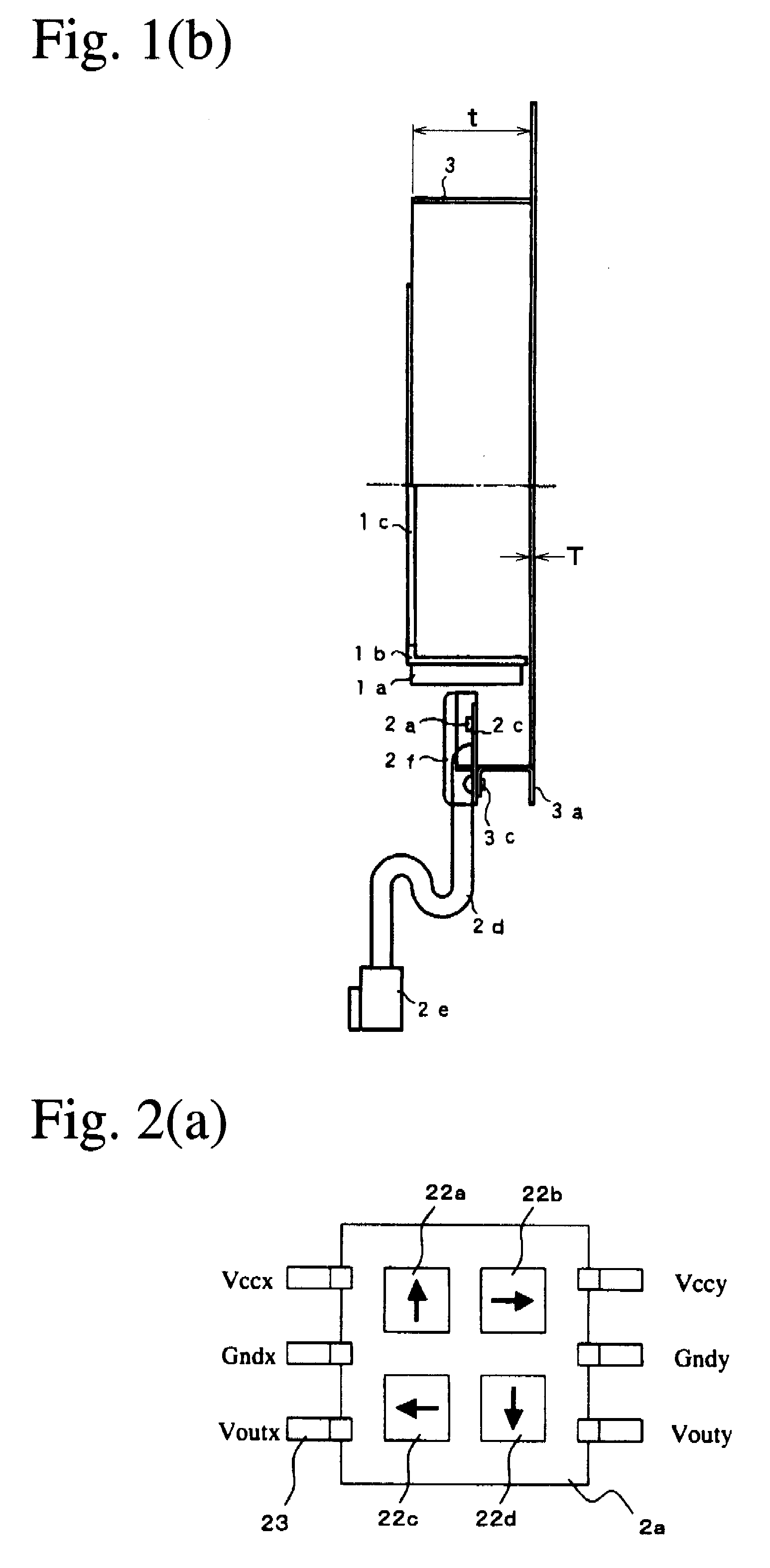
[0270]As shown in FIGS. 1(a) and 1 (b), the first rotation-angle-detecting apparatus of the present invention comprises a magnet rotor 1, a magnetic sensor means 2 arranged outside a periphery of the magnetic rotor, and a housing 3 supporting the magnetic sensor means 2. The magnet rotor 1 comprises a ring-shaped permanent magnet 1a having a periphery in a shape formed by connecting pluralities of arcs, a soft-magnetic ring 1b integrally formed on an inner surface of the ring-shaped permanent magnet, and a non-magnetic, ring-shaped adaptor 1c supporting the soft-magnetic ring. The magnetic sensor means 2 comprises a planar circuit board 2c having a concaved surface facing the magnet rotor 1, a pair of sensor devices 2a, 2b fixed onto the circuit board 2c, a cable 2d and a connector 2e for electrically connecting the sensor devices and the circuit board 2c to a control circuit, and a non-magnetic cover 2f sealing the sensor devices. Each sensor device 2a, 2b has two laminated, spin-v...

example 2

[0284]The second rotation-angle-detecting apparatus of the present invention was produced like the first rotation-angle-detecting apparatus of Example 1, except that the sensor devices 2a, 2b shown in FIGS. 2(a) to 2(d) were changed to resin-molded sensor devices 12a, 12b comprising eight spin-valve, giant-magnetoresistive devices for constituting two full bridge circuits, and 10 terminals 23 formed from a non-magnetic leadframe as shown in FIGS. 9(a) to 9 (f). Even when the distance r shown in FIGS. 1(a) and 1(b) was increased to 10 mm, the apparatus could be used without any trouble. Even when the magnet rotor 1 had a thickness t of 5 mm, there was no trouble, either.

[0285]As shown in FIG. 9(a), one sensor device 12a comprises 8 spin-valve, giant-magnetoresistive devices, each of which has a pinned layer whose magnetization direction is oriented in an X, Y, −X, or −Y direction. A thick arrow in the figure represents a magnetization direction of the pinned layer in one element. Fou...

example 3

[0291]FIGS. 12(a) and 12(b) show another example of the rotation-angle-detecting apparatuses of the present invention comprising a magnet rotor 1 having two magnetic poles on the circumferential surface, and a housing 3 to which a magnetic sensor means 21 supporting a sensor device 12a and a magnetic sensor means 22 supporting a sensor device 12b are fixed. A point O represents a rotation axis of the magnet rotor 1. The two sensor devices 12a, 12b are 90° separate from each other. With the sensor devices 12a, 12b each having two spin-valve, giant-magnetoresistive devices whose pinned layers have magnetization directions perpendicular to each other, the rotation angle of a ring-shaped permanent magnet 1a on the magnet rotor 1 can be detected.

[0292]The magnet rotor 1 comprises the ring-shaped permanent magnet 1a, a soft-magnetic ring 1b integrally formed on an inner surface of the ring-shaped permanent magnet, and a non-magnetic, ring-shaped adaptor 1c supporting the soft-magnetic rin...


PUM


Abstract

A rotation-angle-detecting apparatus comprising a magnet rotor having 4 or more magnetic poles on the surface, and sensor device for detecting magnetic flux from the magnet rotor, and an electronic circuit for outputting a signal representing the rotation angle of the magnet rotor using pluralities of signals obtained from the sensor device, the sensor device having pluralities of spin-valve, giant-magnetoresistive devices for outputting two or more different phase signals from a rotating magnetic field near the rotating magnet, each spin-valve, giant-magnetoresistive device having a pinned layer and a free layer, the magnetization direction of the pinned layer being fixed, and the magnetization direction of the free layer rotating depending on a magnetic field direction, pluralities of the spin-valve, giant-magnetoresistive devices comprising a first spin-valve, giant-magnetoresistive device having a reference magnetic-field-sensing direction, and a second spin-valve, giant-magnetoresistive device having a magnetic-field-sensing direction different from that of the first spin-valve, giant-magnetoresistive device.

Description

FIELD OF THE INVENTION[0001]The present invention relates to an apparatus for detecting the rotation angle of a rotation shaft, etc., a rotating machine, and a method for detecting a rotation angle.BACKGROUND OF THE INVENTION[0002]JP 2003-075108 A discloses a rotation angle sensor comprising a rotating disc-shaped magnet, and pluralities of magnetic sensors arranged near the periphery of the magnet on a plane substantially perpendicular to the rotation centerline of the magnet for detecting a magnetic field to supply an output corresponding to the rotation angle of the magnet. It shows in FIG. 4 a rotation angle sensor comprising a two-pole, disc-shaped, magnet supported by a rotation shaft, and magnetic sensors A and B disposed around the periphery of the magnet. The magnetic sensors A and B are Hall elements for detecting the intensity of a magnetic field to calculate the rotation angle. The magnetic sensors A and B are arranged such that a mechanical angle between a straight line...

Claims


Application Information

Patent Timeline
Patent Type & Authority Applications(United States)
IPC IPC(8): G01B7/30
CPCG01D5/2451G01D5/145
Inventor AIMUTA, KYOHEISHIMOE, OSAMU
Owner HITACHI METALS LTD
Why Eureka
Try Eureka