Illumination device and liquid crystal display device

a technology of liquid crystal display and illumination device, which is applied in the direction of lighting and heating apparatus, instruments, optical elements, etc., can solve the problems of reducing the efficiency of illumination device utilization, increasing and not uniform illumination, so as to achieve the effect of reducing the size and thickness of light source, reliably having directivity, and reducing the thickness of illumination devi

Active Publication Date: 2009-08-20
SHARP KK
View PDF10 Cites 60 Cited by
  • Summary
  • Abstract
  • Description
  • Claims
  • Application Information

AI Technical Summary

Benefits of technology

[0016]However, in a case where the light source is made of a fluorescent tube as in the case of Patent Document 1, an intensity of light that is emitted from the light source is the same in all directions and a light-emitting surface of the illumination device is directly illuminated. Accordingly, unless a light-shielding layer having a considerably large density is provided right above the florescent light directly illuminating the light-emitting surface, illumination does not become uniform. However, the arrangement including such a light-shielding layer reduces efficiency in utilization of light in the illumination device. Further, for obtaining an illumination device whose efficiency is not reduced and that has excellent luminance uniformity, a distance between the light-shielding section and the light sources needs to be large. However, this arrangement increases a thickness of the illumination device.
[0045]The liquid crystal display device of the present invention includes the illumination device of the present invention as described above. This allows the liquid crystal display device of the present invention to have a sufficient luminance and excellent luminance uniformity even in a case where the liquid crystal display device has an increased size and a reduced thickness.

Problems solved by technology

Accordingly, unless a light-shielding layer having a considerably large density is provided right above the florescent light directly illuminating the light-emitting surface, illumination does not become uniform.
However, the arrangement including such a light-shielding layer reduces efficiency in utilization of light in the illumination device.
However, this arrangement increases a thickness of the illumination device.

Method used


Image

  • Illumination device and liquid crystal display device
  • Illumination device and liquid crystal display device
  • Illumination device and liquid crystal display device

Examples


Embodiment Construction

[0065]The following illustratively explains one embodiment of the present invention in details, with reference to drawings. Unless a specific explanation is provided particularly, dimensions, materials, shapes, and relative positions of constituent sections as described in this embodiment are merely illustrative examples and by no means limit the scope of the present invention.

[0066]The present embodiment provides an explanation on an illumination device that is used as a backlight of a liquid crystal display device, with reference to FIGS. 1 through 8.

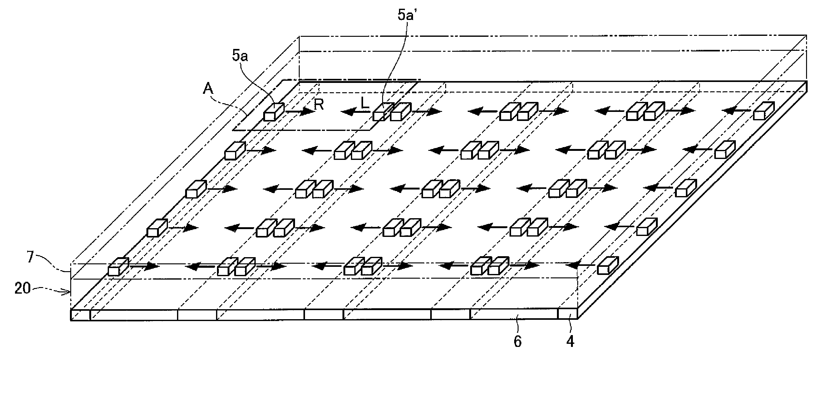
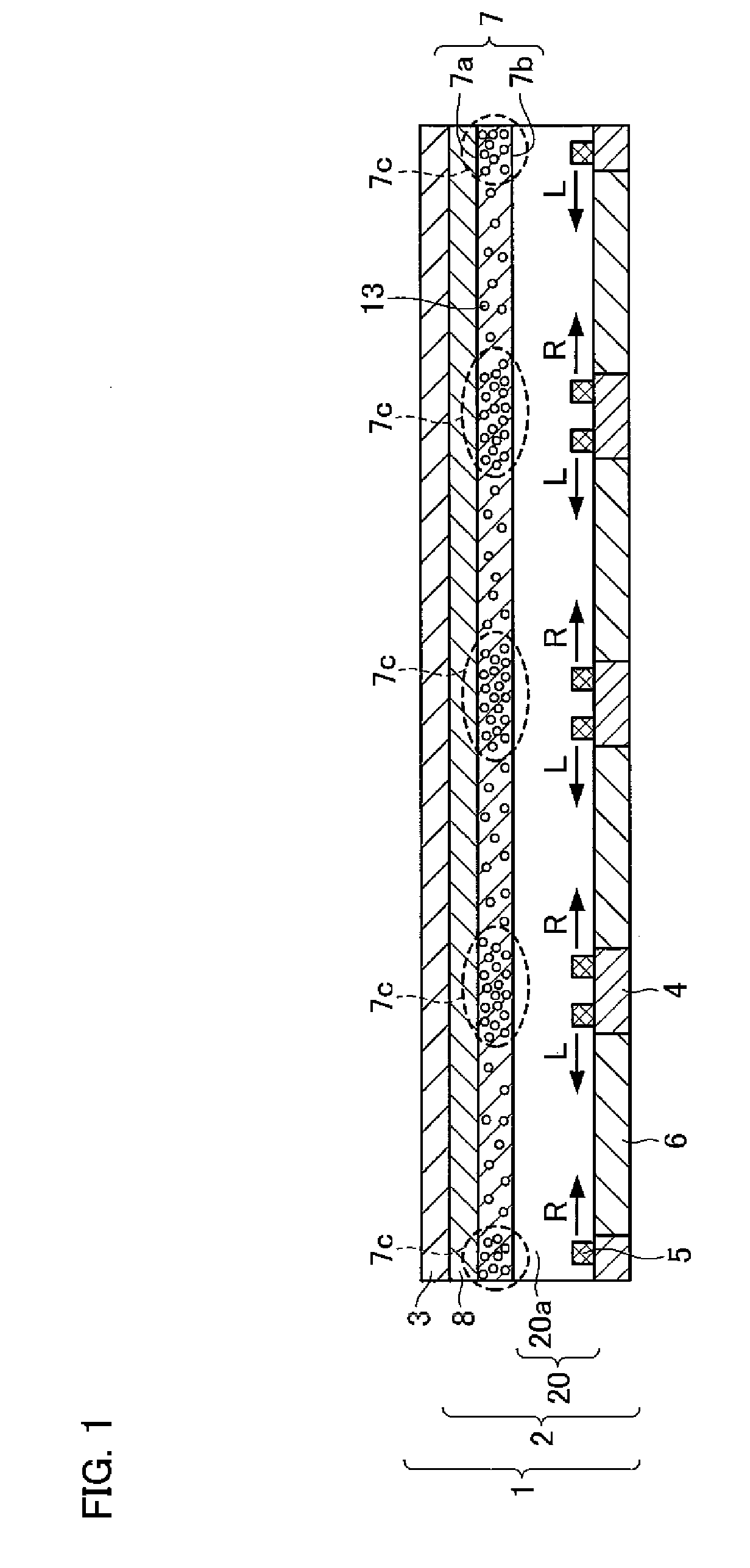
[0067]FIG. 1 shows a liquid crystal display device 1 of the present embodiment. The liquid crystal display device 1 includes a backlight 2 (an illumination device) and a liquid crystal display panel 3. An arrangement of the liquid crystal display panel 3 is the same as a general liquid crystal display panel that is used in a conventional liquid crystal display device, and an explanation thereof is omitted. The following explains in de...


PUM

PropertyMeasurementUnit
thicknessaaaaaaaaaa
transmittanceaaaaaaaaaa
sizeaaaaaaaaaa

Abstract

A liquid crystal display device (1) of the present invention includes a display panel (3) and a backlight (2) (an illumination device). The backlight (2) includes a light-emitting layer (20) in which a plurality of light sources (5) are scattered and a diffuser (7) (a diffusion layer) that is formed on the light-emitting layer and diffuses light from the light-emitting layer. The light sources (5) that are present within the light-emitting layer (20) emit light in a direction (a direction of an arrow) substantially parallel to a boundary surface between the light-emitting layer (20) and the diffuser (7). In the diffuser (7), a transmittance of light in an area (7c) close to each of the light sources is smaller than a transmittance of light in an area that is far from each of the light sources.

Description

TECHNICAL FIELD[0001]The present invention relates to (i) an illumination device that is used as, for example, a backlight of a liquid crystal display device and (ii) a liquid crystal display device including the illumination device.BACKGROUND ART[0002]In recent years, a liquid crystal display device has been prevailing in place of a CRT (Cathode Ray Tube). The liquid crystal display device is widely used as, for example, a liquid crystal television, a monitor, and a mobile phone, by taking advantages such as an energy saving characteristic, a small thickness, and a light weight. Improvement of an illumination device (so-called backlight) that is provided on a backside of the liquid crystal display device is one method for taking such advantages more effectively.[0003]Illumination devices are broadly classified mainly into a sidelight type (an edge-light type) and a direct type. A sidelight type illumination device is provided with a light guide on a backside of a liquid crystal dis...

Claims


Application Information

Patent Timeline
Patent Type & Authority Applications(United States)
IPC IPC(8): G02F1/13357F21V1/00
CPCG02B5/0242G02B5/0278G02B6/0021G02F2001/133613G02B6/0073G02F1/133603G02F1/133611G02B6/0068G02F1/133613
Inventor AJICHI, YUHSAKUMASUDA, TAKESHI
Owner SHARP KK
Why Eureka
Try Eureka