

Stage device, exposure apparatus and method of producing device
a technology of exposure apparatus and stage device, which is applied in the direction of photomechanical treatment, printing, instruments, etc., can solve the problems of reducing the overlay accuracy of the pattern on the substrate, affecting the quality of the substrate, and affecting the appearance accuracy of the substrate, so as to achieve the effect of suppressing temperature change in the mask, suppressing the occurrence of exposure defects, and suppressing the production of defective devices
- Summary
- Abstract
- Description
- Claims
- Application Information
AI Technical Summary
Benefits of technology
Problems solved by technology
Method used
Image

Examples
first embodiment
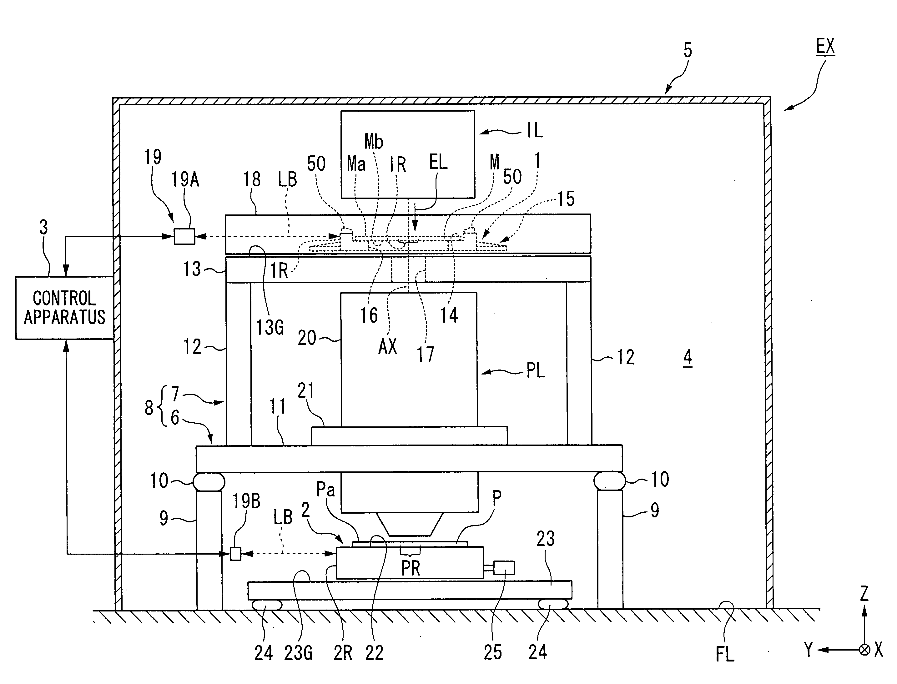
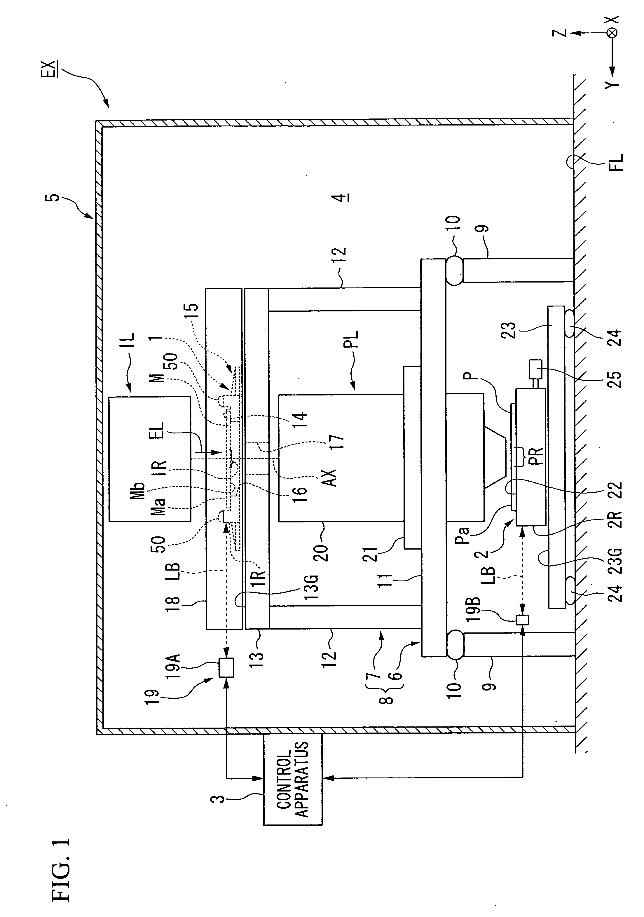
[0028]A first embodiment will be described hereafter. FIG. 1 is a schematic view showing an example of an exposure apparatus EX according to the first embodiment. In FIG. 1, the exposure apparatus EX is provided with a mask stage retaining and moving a mask M, a substrate stage 2 retaining and moving a substrate P, an illumination system IL illuminating the mask M retained on the mask stage 1 with exposure light EL, a projection optical system PL projecting an image pattern of the mask M illuminated by exposure light EL onto the substrate P retained on the substrate stage 2, and a control apparatus 3 controlling the overall operation of the exposure apparatus EX. The control apparatus 3 includes for example a computer system. The exposure apparatus EX includes a chamber apparatus 5 forming an inner space 4 in which the substrate P is processed. The chamber apparatus 5 can regulate the environment of the inner space 4 (temperature, humidity and cleanliness level).
[0029]The substrate ...
second embodiment
[0104]A second embodiment will be described hereafter. In the description below, the constituent sections which are the same or equivalent to those described in the embodiment above are denoted by the same reference numerals and description thereof will be simplified or omitted. In the same manner as the first embodiment above, the intake structure described in each embodiment hereafter functions as an outlet structure in response to the direction of movement of the mask stage 1. The description hereafter will focus on the intake structure and description of the outlet structure will be simplified or omitted.
[0105]FIG. 6 shows an example of a mask stage 1 having an intake structure 50B according to the second embodiment. The intake structure 50B according to the second embodiment includes a turbulence producing mechanism 60 creating turbulence in the gas supplied from the supply port 53. In the embodiment, the turbulence producing mechanism 60 includes a plurality of minute members ...
third embodiment
[0108]A third embodiment will be described hereafter. In the description below, the constituent sections which are the same or equivalent to those described in the embodiments above are denoted by the same reference numerals and description thereof will be simplified or omitted.
[0109]FIG. 8 shows an example of a mask stage 1 according to a third embodiment. The third embodiment may be characterized in the provision of a drive device 63 enabling movement of the nozzle member 54 for adjustment of the positional relationship of the first member 28 and the nozzle member 54.
[0110]In FIG. 8, the intake structure 50D is provided with a drive device 63 enabling movement of the nozzle member 54. In the embodiment the drive device 63 is disposed between the upper face 41 of the first member 28 and the nozzle member 54. The drive device 63 includes an actuator driven by a Lorentz force such as a voice coil motor. The drive device 63 can move the nozzle member 54 with respect to the first membe...
PUM
 Abstract
Description
Claims
Application Information