Dissolution test vessel with rotational agitation

Inactive Publication Date: 2009-08-20
AGILENT TECH INC
View PDF15 Cites 14 Cited by
  • Summary
  • Abstract
  • Description
  • Claims
  • Application Information

AI Technical Summary

Benefits of technology

[0011]According to another implementation, a vessel is mounted at the vessel mounting site of the dissolution test apparatus. A flanged section of the vessel is secured to the rotary member such that the vessel is rotatable with the rotary member about the central axis.
[0012]According to another implementation, a method is provided for agitating dissolution media contained in a vessel mounted at a dissolution test apparatus. A rotary member is secured to a flanged section of the vessel.

Problems solved by technology

Unfortunately, like other instruments that may be inserted into vessels such as fiber-optic probes, conventional instruments utilized to agitate the dissolution media may engender hydrodynamic effects adverse to the acquisition of accurate dissolution data.
Additionally, the presence of such instruments in the vessels impairs visual inspe

Method used


Image

  • Dissolution test vessel with rotational agitation
  • Dissolution test vessel with rotational agitation
  • Dissolution test vessel with rotational agitation

Examples


Embodiment Construction

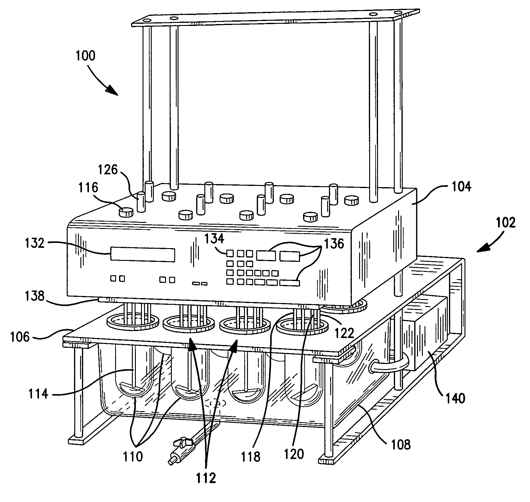
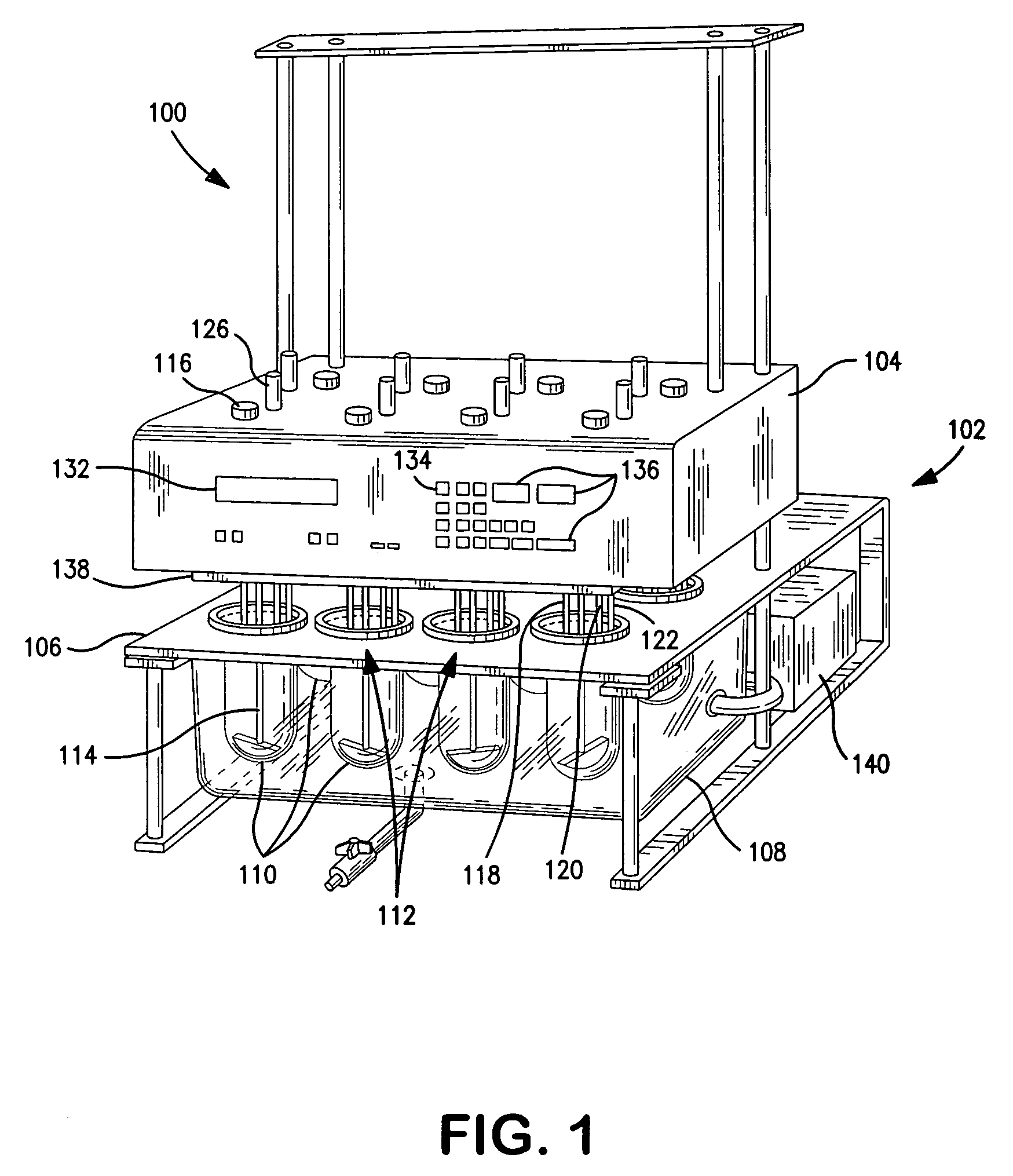
[0022]FIG. 1 is a perspective view of an example of a dissolution test apparatus 100 according to an implementation of the present disclosure. The dissolution test apparatus 100 may include a frame assembly 102 supporting various components such as a main housing, control unit or head assembly 104, a vessel support member (e.g., a plate, rack, etc.) 106 below the head assembly 104, and a water bath container 108 below the vessel support member 106. The vessel support member 106 supports a plurality of vessels 110 extending into the interior of the water bath container 108. FIG. 1 illustrates eight vessels 110 by example, but it will be understood that more or less vessels 110 may be provided. Conventionally, the vessels 110 may be locked and centered in place on the vessel support member 106 by means such as ring lock devices or clamps (not shown) at a plurality of vessel mounting sites 112. Alternatively, the vessels 110 themselves may be configured to have centering capability, as...


PUM

PropertyMeasurementUnit
Speedaaaaaaaaaa

Abstract

A rotatable vessel includes a rotary member secured to a vessel body and drivable to rotate the vessel about a central axis. The rotary member may be supported by a bearing at a dissolution test apparatus at which the vessel is mounted. The dissolution test apparatus may include a drive system coupled to the rotary member for driving the rotation of the vessel at a desired speed or according to a desired speed profile. The rotation of the vessel agitates media contained in the vessel, thus eliminating the need for a stirring element operating within the vessel.

Description

CROSS REFERENCE TO RELATED APPLICATIONS[0001]This application is related to the dissolution testing of analyte-containing media as well as following U.S. patent applications titled “Dissolution Test Vessel with Integrated Centering Geometry” and “Captive Evaporation Cover for Dissolution Systems”, which are commonly assigned by the same inventor to the assignee of the present disclosure. These U.S. patent applications are being filed concurrently with the present patent application on Feb. 14, 2008.FIELD OF THE INVENTION[0002]The present invention relates generally to dissolution testing of analyte-containing media. More particularly, the present invention relates to rotation of a vessel utilized to contain dissolution media.BACKGROUND OF THE INVENTION[0003]Dissolution testing is often performed as part of preparing and evaluating soluble materials, particularly pharmaceutical dosage forms (e.g., tablets, capsules, and the like) consisting of a therapeutically effective amount of ac...

Claims


Application Information

Patent Timeline
IPC IPC(8): B01F1/00B01L3/00B01J19/00
CPCB01F1/00G01N33/15B01L7/02B01F9/10B01F21/00B01F29/80
Inventor FETVEDT, JEREMY
Owner AGILENT TECH INC
Why Eureka
Try Eureka