Ribbon for ribbon microphone, manufacturing method of the same, and ribbon microphone

a ribbon microphone and microphone technology, applied in the direction of magnets, cores/yokes, magnets, etc., can solve the problems of insufficient rigidity of the ribbon, inability to convert sound waves into electric signals with fidelity, and inability to achieve the effect of reducing the frequency response, and improving the rigidity

Active Publication Date: 2009-08-20
AUDIO-TECHNICA
View PDF1 Cites 7 Cited by
  • Summary
  • Abstract
  • Description
  • Claims
  • Application Information

AI Technical Summary

Benefits of technology

[0018]If the ribbon is comprised only of the patterns of the large waveform which are formed so as to progress in the longitudinal direction of the ribbon and are formed in a manner that the ridge lines face the direction which perpendicularly cross the longitudinal direction of the ribbon, the partial resonance occurs as mentioned above. However, by forming the small patterns smaller than the patterns of the waveform along the longitudinal direction of the ribbon together with the large patterns, concave and convex portions according to the small patterns are also formed in the portions corresponding to the half period of the waveform, so that the rigidity increases and the occurrence of the partial resonance is suppressed. Therefore, if the ribbon microphone is constructed by assembling the ribbon into the ribbon microphone unit and by assembling the microphone unit into a microphone case, it is suppressed that the sharp resonance appears in the frequency response characteristics, and the good frequency response characteristics can be obtained.
[0019]According to the manufacturing method of the ribbon for the ribbon microphone of the invention, in spite of a fact that the ribbon has the complicated shape comprised of the patterns of the large waveform which progress in the longitudinal direction and the small patterns which are smaller than the patterns of the waveform and are arranged in the longitudinal direction of the ribbon, the ribbon for the ribbon microphone can be easily manufactured merely by transferring the surface shape of the transfer mold to the material of the ribbon. According to the transfer mold, since the patterns of the large waveform are formed by the cutting process and the small patterns are formed by the etching process, the transfer mold can be also easily manufactured.

Problems solved by technology

Therefore, a problem exists in that the resonance appears in the frequency response and the sound wave cannot be converted into the electric signal with fidelity. FIG. 8 illustrates a state of occurrence of a partial resonance in the ribbon formed in such a manner that the directions of the lines drawn by the top and the bottom of the triangular wave coincide with the width direction in the whole length direction.
However, even if the shape such as embossing finished or satin finished shape is formed, the rigidity of the ribbon cannot be sufficiently increased and the problem of the partial resonance cannot be solved.

Method used


Image

  • Ribbon for ribbon microphone, manufacturing method of the same, and ribbon microphone
  • Ribbon for ribbon microphone, manufacturing method of the same, and ribbon microphone
  • Ribbon for ribbon microphone, manufacturing method of the same, and ribbon microphone

Examples


Embodiment Construction

[0029]Embodiments of a ribbon for a ribbon microphone according to the invention, a manufacturing method of the ribbon, and the ribbon microphone will be described hereinbelow with reference to the drawings.

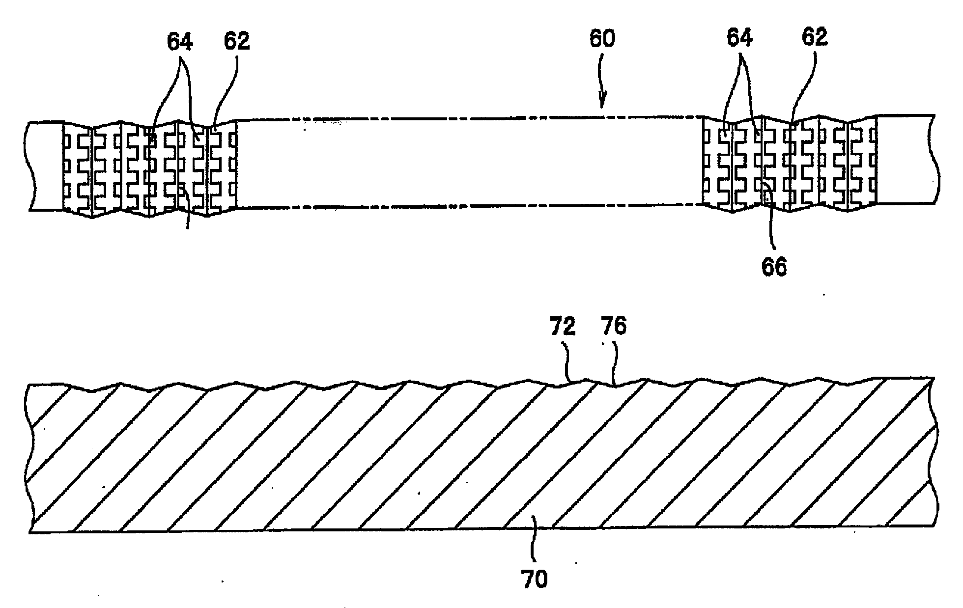
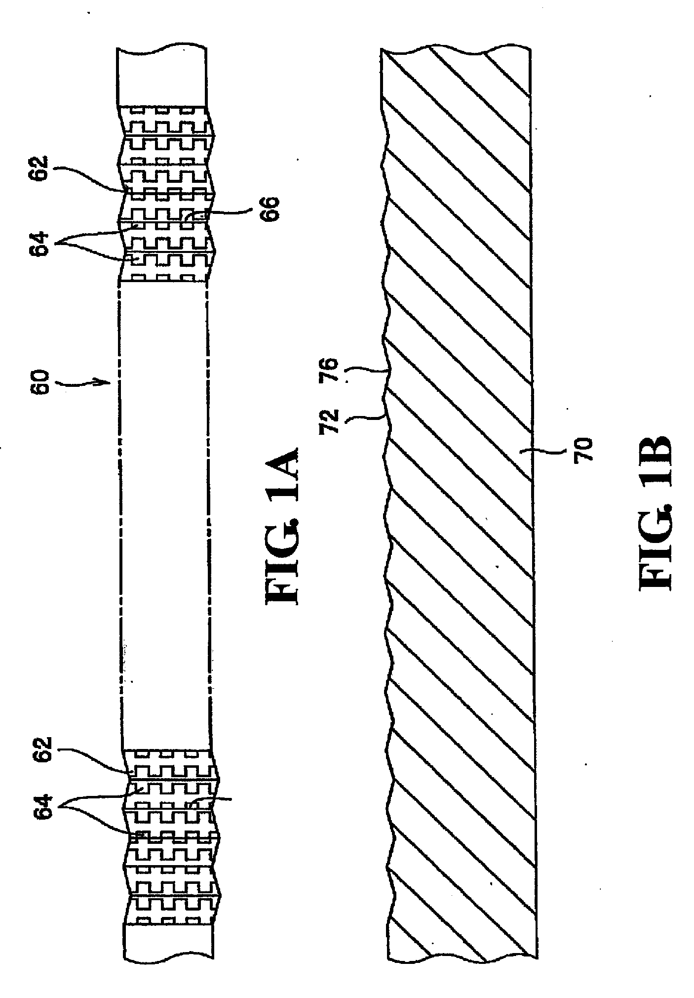
[0030]FIG. 1A shows an embodiment of the ribbon for the ribbon microphone (hereinbelow, referred to as a “ribbon”) according to the present invention. FIG. 1B shows an example of a transfer mold for embodying one of manufacturing steps of the ribbon. In FIG. 1A, a ribbon 60 is made of metal foil such as aluminum foil having a thickness of a few μm. Patterns 62 of a large waveform; and patterns 64 each of which is smaller than the pattern 62 having such a waveform and is formed along the longitudinal direction of the ribbon 60 are formed on the ribbon 60 (hereinbelow, such patterns are referred to as “small patterns”). The pattern 62 of the large waveform has a cross sectional shape of a triangular waveform and is formed so as to progress in the longitudinal direction of the ribbo...


PUM

PropertyMeasurementUnit
depthaaaaaaaaaa
surface shapeaaaaaaaaaa
frequency responseaaaaaaaaaa

Abstract

A ribbon for a ribbon microphone having a magnet forming a magnetic gap, the ribbon which is arranged in the magnetic gap and is vibrated by a sound wave, an electrode for outputting an electric signal which is generated when the ribbon vibrates in the magnetic gap, and a frame for holding the magnet and the electrode; the ribbon has patterns of a large waveform which are formed so as to progress in a longitudinal direction of the ribbon and are formed so that ridge lines face a direction which perpendicularly crosses the longitudinal direction of the ribbon, and small patterns which are smaller than the patterns of the waveform and are formed along the longitudinal direction of the ribbon.

Description

BACKGROUND OF THE INVENTION[0001]1. Field of the Invention[0002]The invention relates to a ribbon for a ribbon microphone which can reduce deterioration of a frequency response caused by a partial resonance of the ribbon, a manufacturing method of the same, and the ribbon microphone.[0003]2. Description of the Related Art[0004]A ribbon microphone is mainly comprised of magnets for forming a magnetic field and a ribbon. The magnets are supported on both sides of a frame so as to sandwich the ribbon and the magnetic field is formed between the magnets on both sides. The ribbon is arranged in the magnetic field in a state where a proper tension has been applied to the ribbon and both edge portions in the length direction have been pressed. When the ribbon receives a sound wave and vibrates in the magnetic field, a current according to the sound wave flows in the ribbon and the sound wave is converted into an electric signal. Hitherto, aluminum foil has widely been used as a material of...

Claims


Application Information

Patent Timeline
Patent Type & Authority Applications(United States)
IPC IPC(8): H04R25/00H01F7/02H01F3/04
CPCH04R9/048Y10T29/4908H04R9/08
Inventor AKINO, HIROSHI
Owner AUDIO-TECHNICA
Why Eureka
Try Eureka