Controlled Perspective Guidance Method

a technology of perspective guidance and control, applied in the direction of diagnostic recording/measuring, instruments, applications, etc., can solve the problem of not gleaned particularly useful information from images, and achieve the effect of more useable visual presentations

Active Publication Date: 2009-08-20
TYCO HEALTHCARE GRP LP
View PDF7 Cites 57 Cited by
  • Summary
  • Abstract
  • Description
  • Claims
  • Application Information

AI Technical Summary

Benefits of technology

[0009]The system and method of the present invention provides more useable visual presentation to a physician using an intra-body navigation system. Generally, the system and method

Problems solved by technology

Hence, no particularly useful information is glean

Method used


Image

  • Controlled Perspective Guidance Method
  • Controlled Perspective Guidance Method
  • Controlled Perspective Guidance Method

Examples


Embodiment Construction

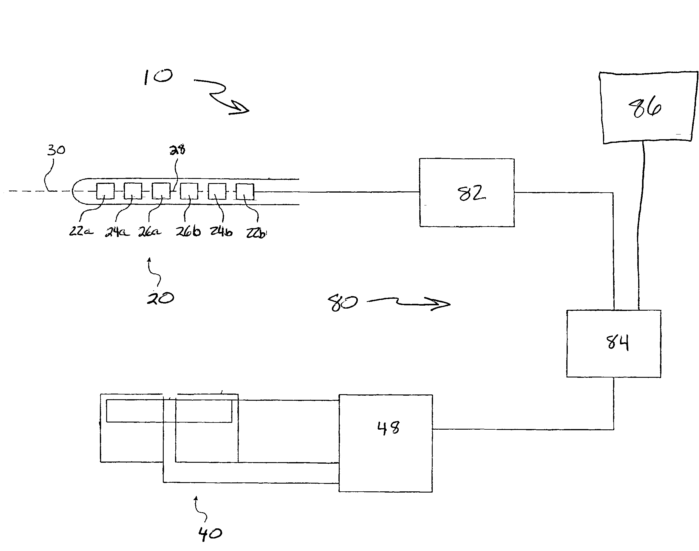
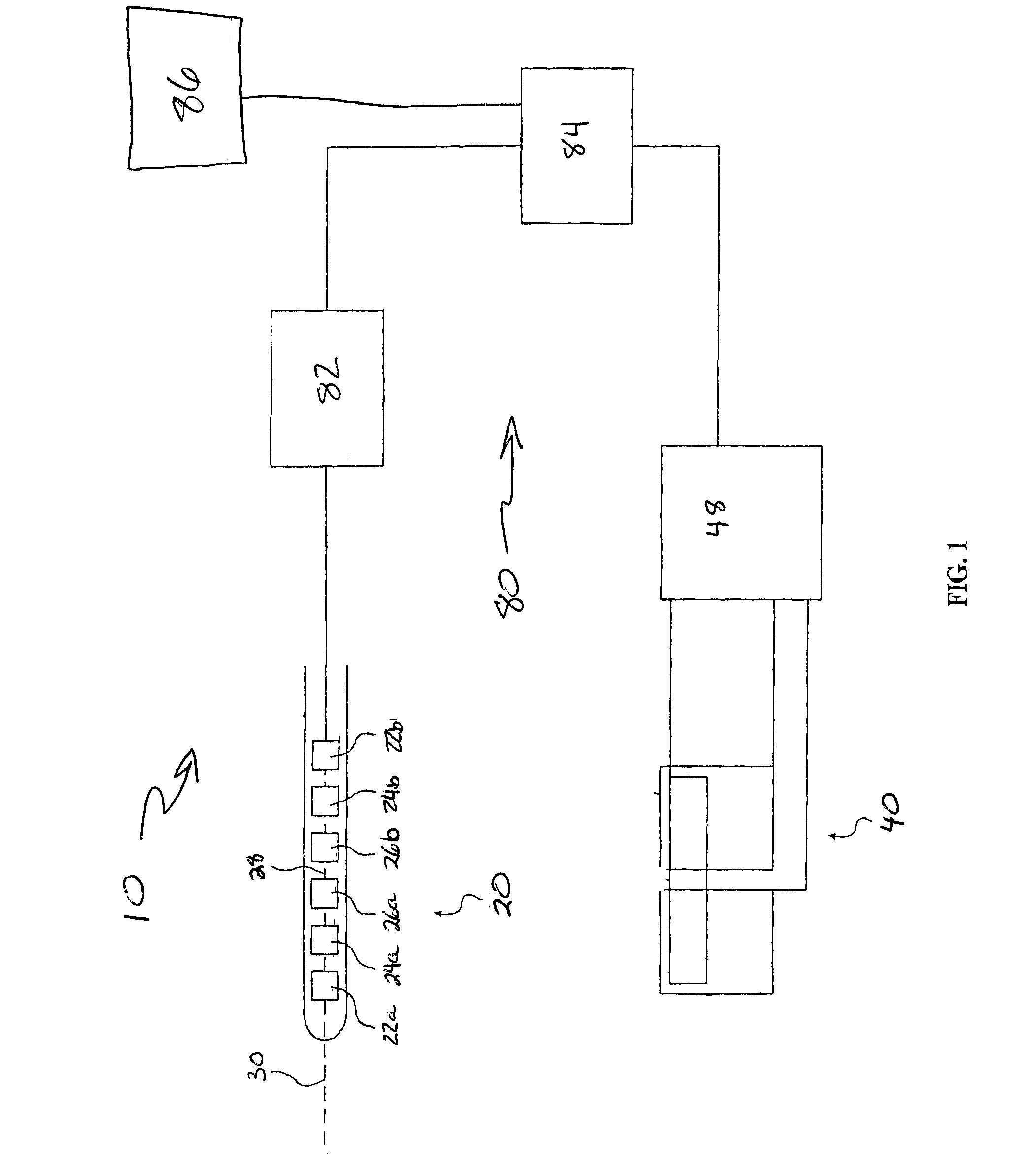
[0017]Referring now to the figures and first to FIG. 1, there is shown a location system 10. Though the navigation display system and method of the present invention may be used with any location system having virtual capabilities, a description of a location system 10 is provided by way of example.

[0018]The location system 10 generally includes a locatable guide 20, a location board 40, and a control system 80. The locatable guide 20 is a probe having a receiver that generally includes a plurality of (preferably three) field component sensors 22, 24 and 26. Each of the field sensor components is arranged for sensing a different component of an electromagnetic field generated by the location board 40.

[0019]The location system 10 also includes the location board 40. The location board 40 is a transmitter of electromagnetic radiation. The location board 40 includes a stack of three substantially planar rectangular loop antennas 42, 44 and 46 connected to drive circuitry 48. Drive circ...


PUM


Abstract

Navigation through a network of body passages, such as through the airways, is improved by a method of displaying information which provides a fly-through visualization of the passageway. As landmarks or waypoints are passed, the view changes to a next segment in a planned pathway to a target. Such a visualization technique avoids tunnel vision, such as that encountered while using real-time endoscopes.

Description

RELATED APPLICATIONS[0001]This application claims priority to U.S. Provisional Application Ser. No. 61 / 028,098 filed Feb. 12, 2008 entitled Controlled Perspective Guidance Method, which is hereby incorporated herein by reference.BACKGROUND OF THE INVENTION[0002]Identifying and treating lung tissue abnormalities presents challenges that are somewhat unique to the lungs. If a tissue lesion or tumor is to be identified and excised surgically, the chest wall must be opened to provide access to the lungs. Opening the chest wall is a common procedure but one that presents risks of infection and lengthy recovery time, nonetheless.[0003]A desirable alternative to surgery, in terms of reducing patient trauma, is to identify and excise the tumor endoscopically. Endoscopic surgery in the lungs, however, means that the complicated bronchial maze must be navigated. Endoscopes have cameras at their distal tips that provide a physician a real-time image through the end of the endoscope while the e...

Claims


Application Information

Patent Timeline
IPC IPC(8): A61B1/00G06T15/00
CPCA61B1/00009A61B5/065G06T19/003A61B2019/5251A61B5/066A61B19/5244A61B34/20A61B2034/2051A61B1/000094
Inventor AVERBUCH, DORIAN
Owner TYCO HEALTHCARE GRP LP
Why Eureka
Try Eureka