Apparatus and method for real-time motion-compensated magnetic resonance imaging

a magnetic resonance imaging and motion compensation technology, applied in the field of medical imaging, can solve the problems of increasing exam costs, reducing clinical yield, and no general correction scheme exists

Inactive Publication Date: 2009-08-20
THE BOARD OF TRUSTEES OF THE LELAND STANFORD JUNIOR UNIV
View PDF14 Cites 129 Cited by
  • Summary
  • Abstract
  • Description
  • Claims
  • Application Information

AI Technical Summary

Problems solved by technology

Motion artifacts cause repeated or non-diagnostic exams, contributing to increased exam costs and diminishing clinical yield.
However, these methods must still be developed on a per-sequence basis; no general correction scheme yet exists.
Further, most methods are retrospective, and cannot compensate for spin history effects; only some can synthesize the missing k-space data after correction.
As these cameras were not MR-compatible, they needed to be positioned as far away from the MRI device as possible.
This setup has pronounced visibility concerns, as the cameras must view any markers through the length of the bore, and past the patient and any coils.
These are extreme limitations, especially for patients with large girths and long bore magnets.

Method used


Image

  • Apparatus and method for real-time motion-compensated magnetic resonance imaging
  • Apparatus and method for real-time motion-compensated magnetic resonance imaging
  • Apparatus and method for real-time motion-compensated magnetic resonance imaging

Examples


example

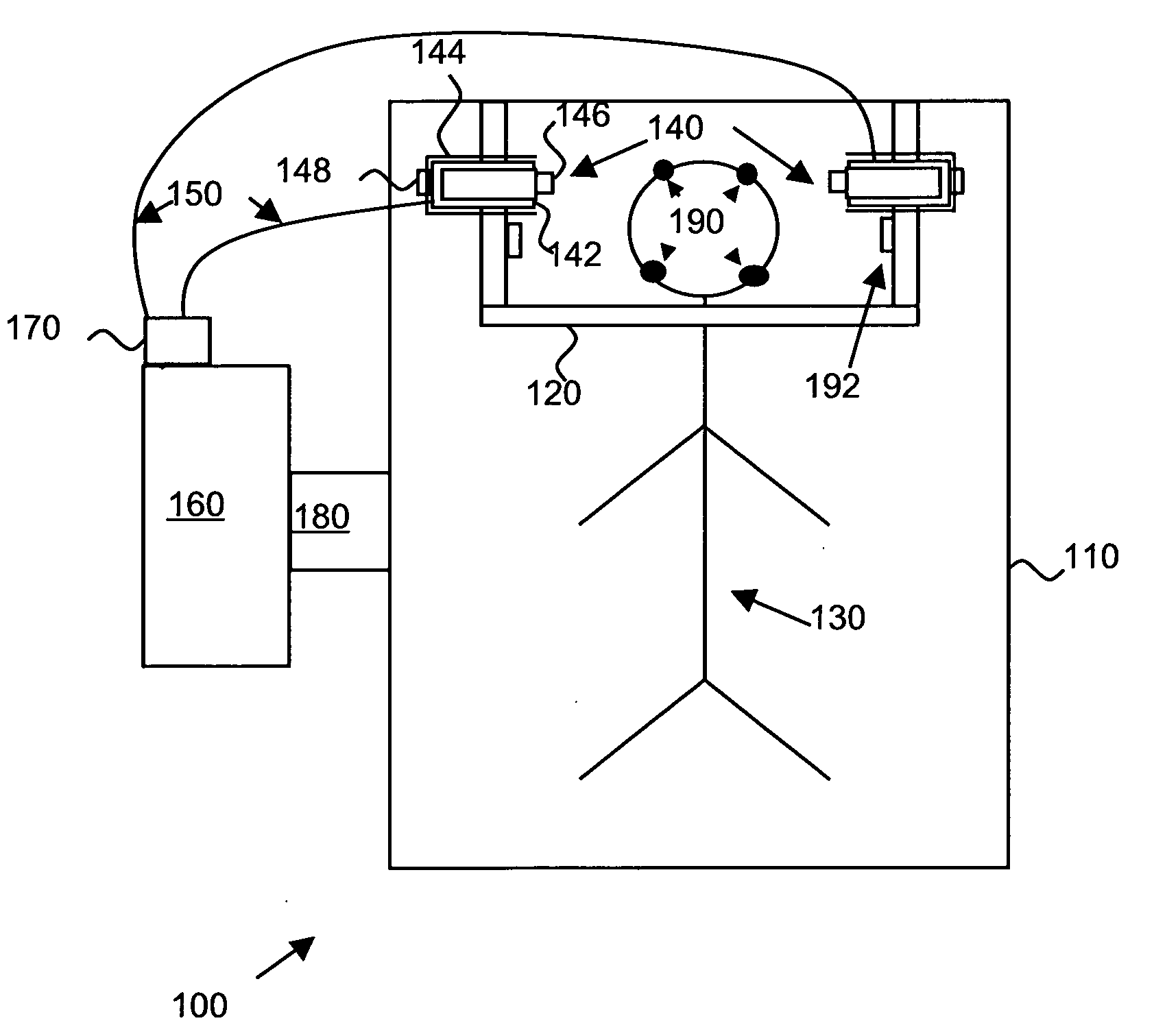
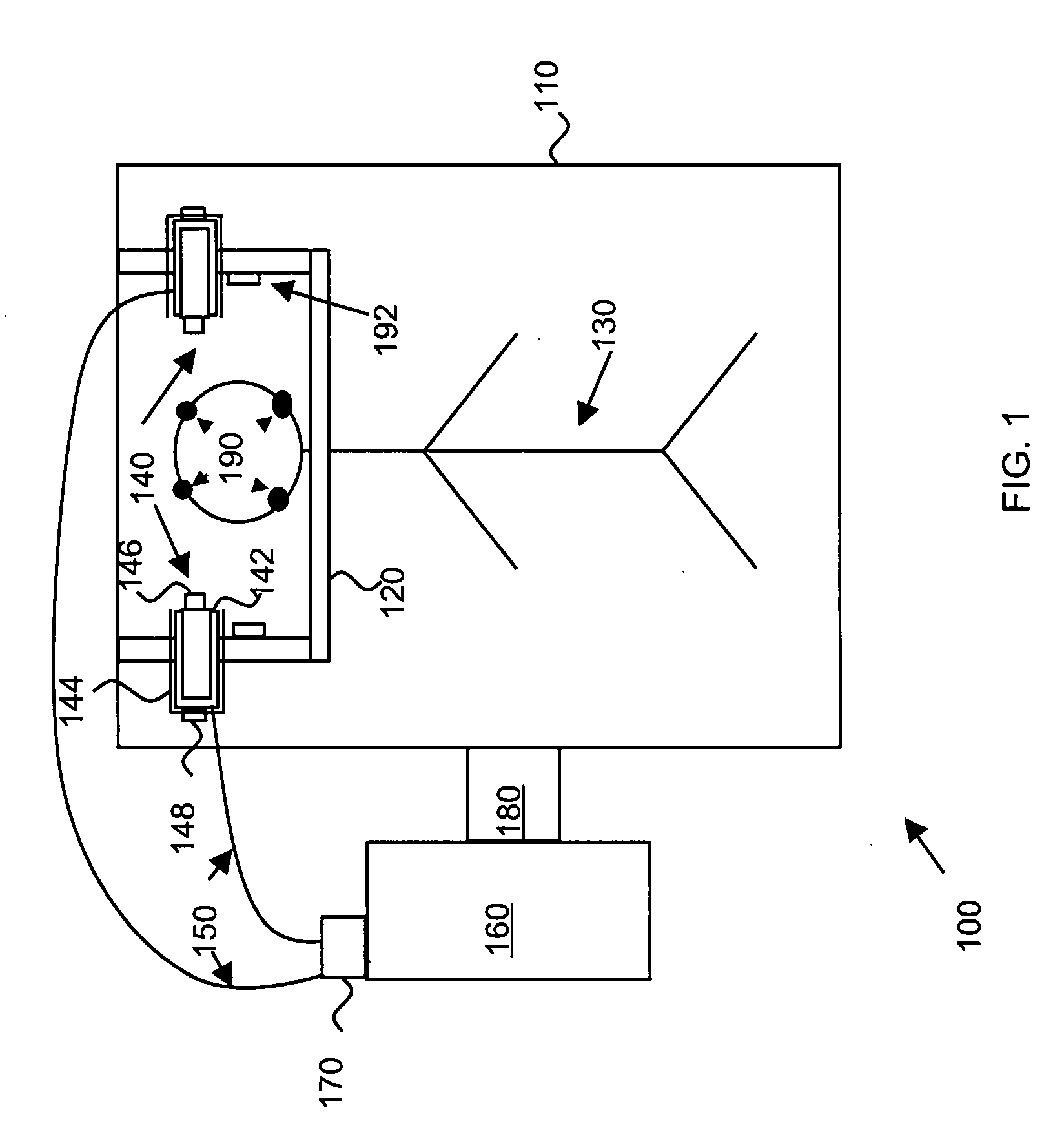
[0046]FIG. 4 shows an example of an MR-compatible CCD imager according to the present invention. The camera shown in FIG. 4 was constructed from a pinhole lens, wide angle (˜75°) “spy cam” with automatically adjustable iris for variable lighting conditions. The camera was selected amongst several other types because of its high image quality, lack of additionally required lighting (i.e. the illumination inside the bore is sufficient), and the negligible magnetic susceptibility changes after highly magnetically susceptible parts were removed, and the remaining circuitry was shielded. Technical specifications of the camera were as follows: ⅓″ solid state interline non-CMOS CCD-BW chip; scanning system: EIA 525 lines, 2:1 interlacing; shutter / exposure: automatically selected, 1 / 60-1 / 100,000 sec; luminance SNR: >45 db; Sensitivity: 0.1 Lux; input voltage: 9-12 volts @ 100 mA; size: 25×25 mm2; 380 TV lines; 3.6 mm pinhole lens. This camera currently operates inside the bore of a 1.5 T MR...


PUM


Abstract

The present invention provides an apparatus and method for real-time motion compensated magnetic resonance imaging (MRI) of a human or animal. The apparatus includes one or more magnetic-resonance compatible cameras mounted on a coil of the MRI device, a calculation and storage device, and an interface operably connected to the MRI device and the calculation and storage device. The apparatus may also include a set of magnetic resonance compatible markers, where the markers are positioned on the human or animal. Alternatively, the apparatus may use a facial recognition algorithm to identify features of the human or animal. For the present invention, the frame of reference is defined by the animal or human being imaged, instead of the typical magnetic resonance coordinate system. Based on continuous positional information, the apparatus controls the magnetic resonance scanner so that it follows the human or animal's motion.

Description

CROSS-REFERENCE TO RELATED APPLICATIONS[0001]This application claims priority from U.S. Provisional Patent Application No. 60 / 817,490, filed Jun. 28, 2006, which is incorporated herein by reference.STATEMENT REGARDING FEDERALLY SPONSORED RESEARCH OR DEVELOPMENT[0002]This invention was made in part with government support under grant nos. R01-EB002771, R21 EB 00680 and P41RR09784 awarded by the National Institutes of Health (NIH). The government has certain rights in this invention.FIELD OF THE INVENTION[0003]The present invention relates generally to medical imaging. More particularly, the present invention relates to an apparatus and method for real-time motion-compensated magnetic resonance imaging.BACKGROUND[0004]Due to the sequential nature of the magnetic resonance imaging (MRI) acquisition process, motion artifacts remain one of the most prevalent confounders of MR studies. Motion artifacts cause repeated or non-diagnostic exams, contributing to increased exam costs and dimini...

Claims


Application Information

Patent Timeline
Patent Type & Authority Applications(United States)
IPC IPC(8): A61B5/055G06K9/00
CPCA61B5/055A61B5/064A61B5/1127G01R33/5673G01R33/56308G01R33/56509A61B5/7207
Inventor BAMMER, ROLAND
Owner THE BOARD OF TRUSTEES OF THE LELAND STANFORD JUNIOR UNIV
Why Eureka
Try Eureka