Vertebral Fixation Plate Assembly

a fixation plate and vertebral technology, applied in the field of vertebral body replacement and vertebral reconstruction, can solve the problems of insufficient function of two different types of fixation devices in clinical practice, inability to carry autograft bone, bone allograft or biomedical bone substitute, etc., to prevent vertebral sinking or slipping, improve bone fusion efficiency, and strengthen the stability of the patient's vertebral column

Inactive Publication Date: 2009-08-20
NAT TAIWAN UNIV OF SCI & TECH
View PDF4 Cites 21 Cited by
  • Summary
  • Abstract
  • Description
  • Claims
  • Application Information

AI Technical Summary

Benefits of technology

[0007]The present invention has been accomplished under the circumstances in view. It is therefore the main object of the present invention to provide a vertebral fixation plate assembly, which is designed for insertion into the resection site between two vertebrae of a patient where a vertebral spacer is implanted and fixation to front or lateral side of the vertebra bodies above and below the resection site to reinforce the stability of the patient's vertebral column. It is another object of the present invention to provide a vertebral fixation plate assembly, which is provided with a bone fusion cage for connection with the vertebral spacer to prevent vertebral sinking or slipping of the vertebral spacer to improve bone fusion efficiency.

Problems solved by technology

However, these two different types of fixation devices are still not satisfactory in function in clinical practice due to the drawbacks: (1) A fixation plate type fixation device wears quickly with use and may be loosed from the bone screws due to thin and weak border edge around each mounting hole, affecting fixation stability and bone fusion progress; (2) A fixation rod type fixation device requires installation of two sets of transverse links to achieve the desired strength and stiffness, complicating the implantation procedure.
Further, conventional fixation devices have no means for carrying autograft bone, bone allograft or biomedical bone substitute to facilitate bone fusion.

Method used


Image

  • Vertebral Fixation Plate Assembly
  • Vertebral Fixation Plate Assembly
  • Vertebral Fixation Plate Assembly

Examples


Embodiment Construction

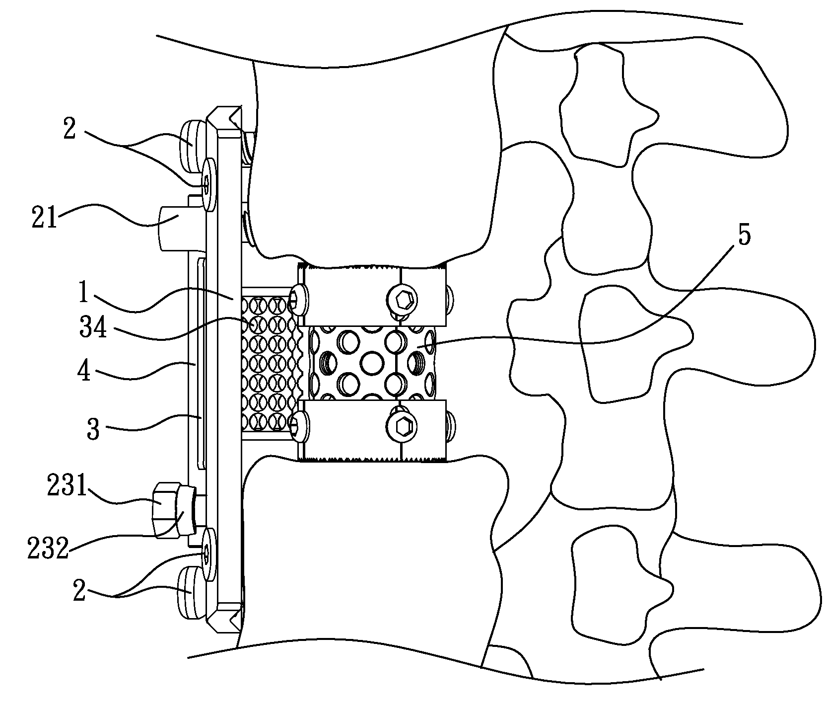
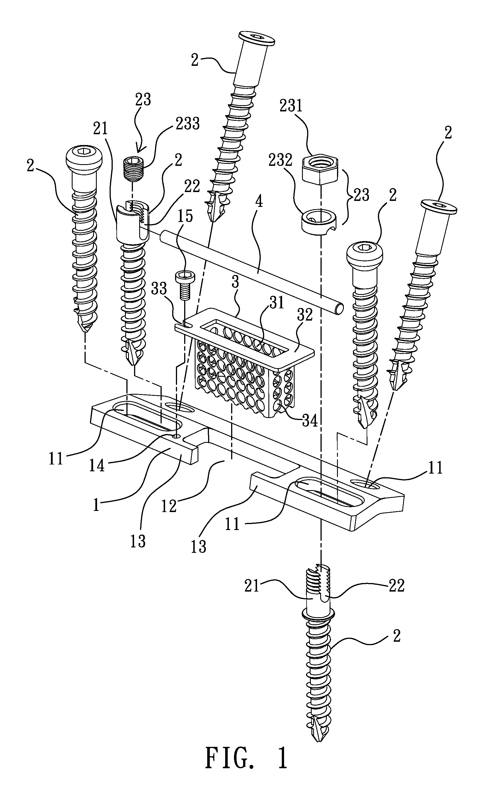
[0016]Referring to FIGS. 1-5, a vertebral fixation plate assembly in accordance with the present invention is for use in a patient whose thoracic or lumbar vertebrae lose the support function. The vertebral fixation plate assembly is inserted into a resection site between two vertebrae of a patient's vertebral and then affixed to the front or lateral side of the two adjacent vertebral bodies above and below the resection site during a surgical operation, enabling the vertebral column to support the patient's body. The vertebral fixation plate assembly is comprised of a fixation plate 1, a plurality of bone screws 2, a cage 3, and a link 4.

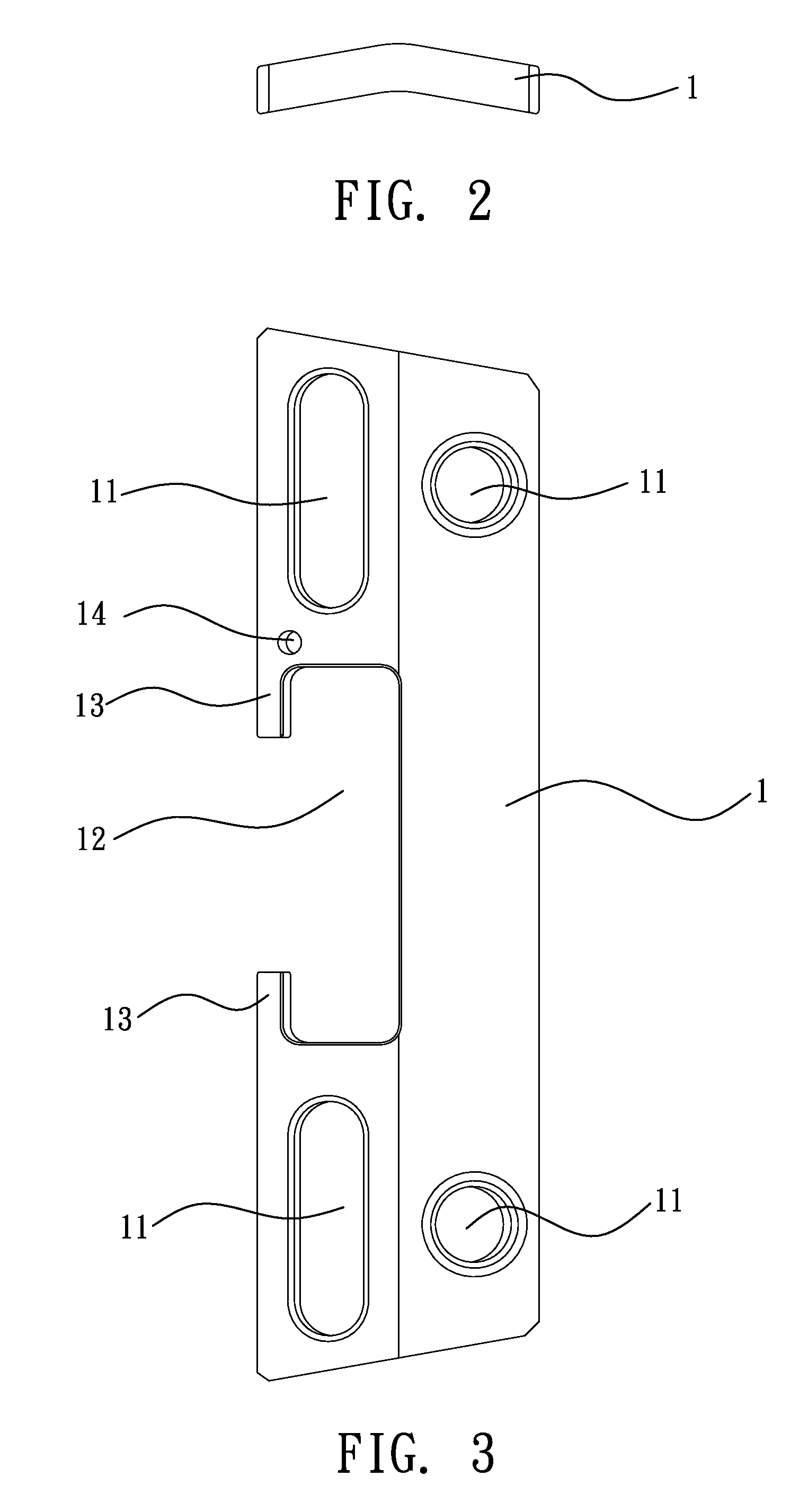
[0017]The fixation plate 1 can be a metal plate made of, for example, titanium. Following fast development of biomedical material technology, many biomedical materials have been proved suitable for making the fixation plate. For example, PEEK (polyetheretherketone) may be used. As shown in FIG. 2, the fixation plate 1 has a symmetrically arched cro...


PUM


Abstract

A vertebral fixation plate assembly for insertion into the resection site between two vertebrae of a patients vertebral column and fixation to front or lateral side of the two adjacent vertebral bodies above and below the resection site by means of surgical implantation is disclosed to include a fixation plate that has a plurality of round holes and elongated holes and an opening on the middle, a plurality of bone screws respectively inserted through the round holes and elongated holes for fastening the fixation plate to the patient's vertebral column, and a cage affixed to the opening on the fixation plate and holding holes cut through the periphery for bone fusion and grow. The cage is linked to a vertebral spacer for artificial vertebrae by means of bone fusion to prevent vertebral sinking or slipping of the vertebral spacer and to improve bone fusion efficiency.

Description

BACKGROUND OF THE INVENTION[0001]1. Field of the Invention[0002]The present invention relates to vertebral reconstruction and vertebral body replacement and more particularly, to a vertebral fixation plate assembly for fixation of thoracic or lumber vertebrae that improves bone fusion efficiency.[0003]2. Description of the Related Art[0004]Vertebral reconstruction and vertebral body replacement commonly uses a vertebral spacer to treat (substitute for) vertebrae destruction or vertebral body damaged by tumor. By means of surgical operation to remove disease vertebral body, a vertebral spacer is inserted into the resection site, and then a fixation device is affixed to the front or lateral side of the vertebral column with pedicle screws to enhance the stability, enabling the vertebral column to resume its function, reducing the patient's pain, and assisting recovery.[0005]Regular fixation devices for this purpose include two types, the fixation plate and the fixation rod. However, t...

Claims


Application Information

Patent Timeline
Patent Type & Authority Applications(United States)
IPC IPC(8): A61B17/70A61B17/58
CPCA61B17/7032A61B17/7044A61F2002/30784A61F2/44A61F2002/2835A61B17/7059
Inventor CHAO, CHING-KONGHSU, WEN-HSIENHSU, CHING-CHIHSU, HSI-CHINGTSAI, YU-HSIANG
Owner NAT TAIWAN UNIV OF SCI & TECH
Why Eureka
Try Eureka