

HDMI logical address assignment method for use in wireless communication system
- Summary
- Abstract
- Description
- Claims
- Application Information
AI Technical Summary
Benefits of technology
Problems solved by technology
Method used
Image

Examples
first preferred embodiment
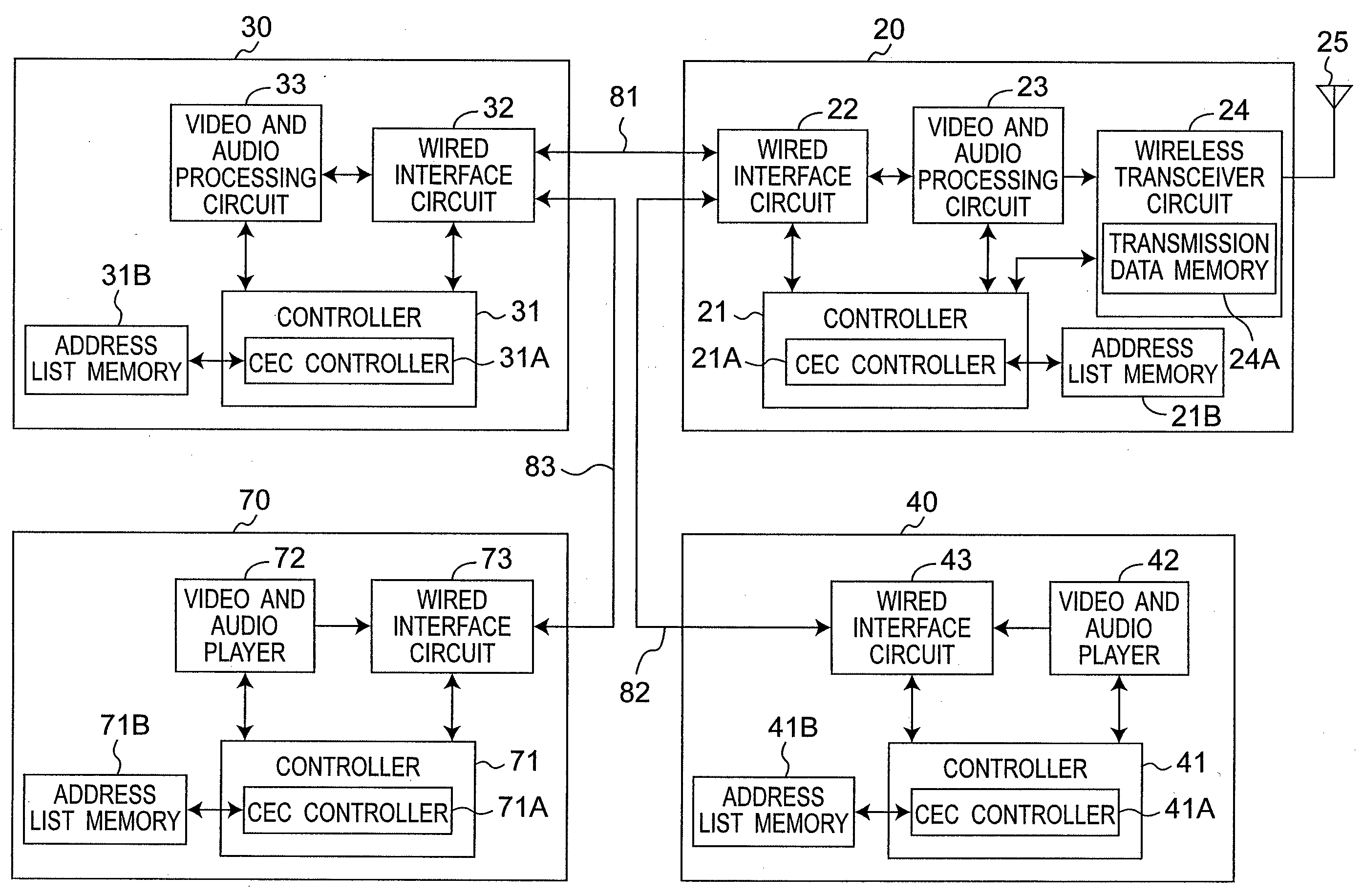
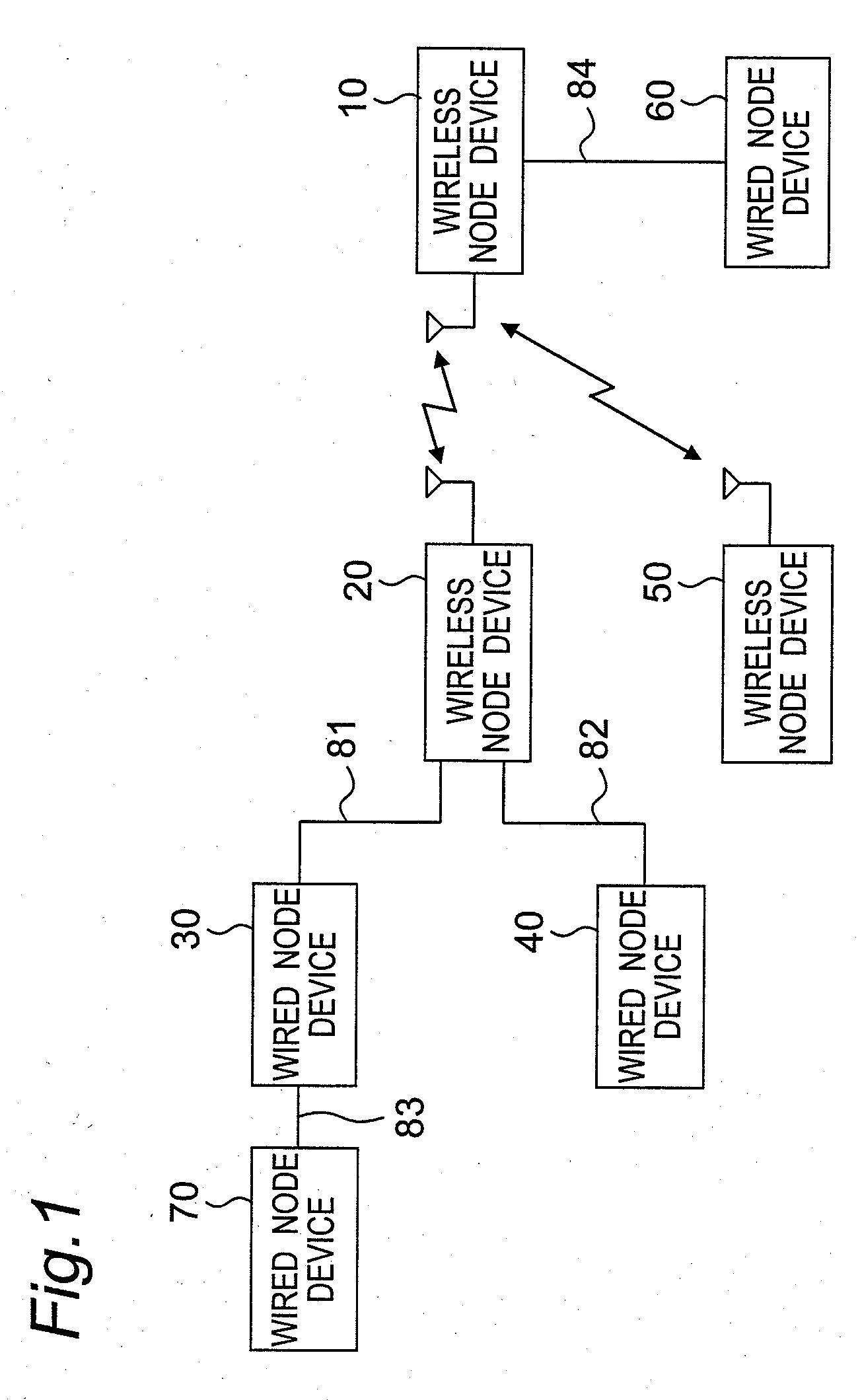
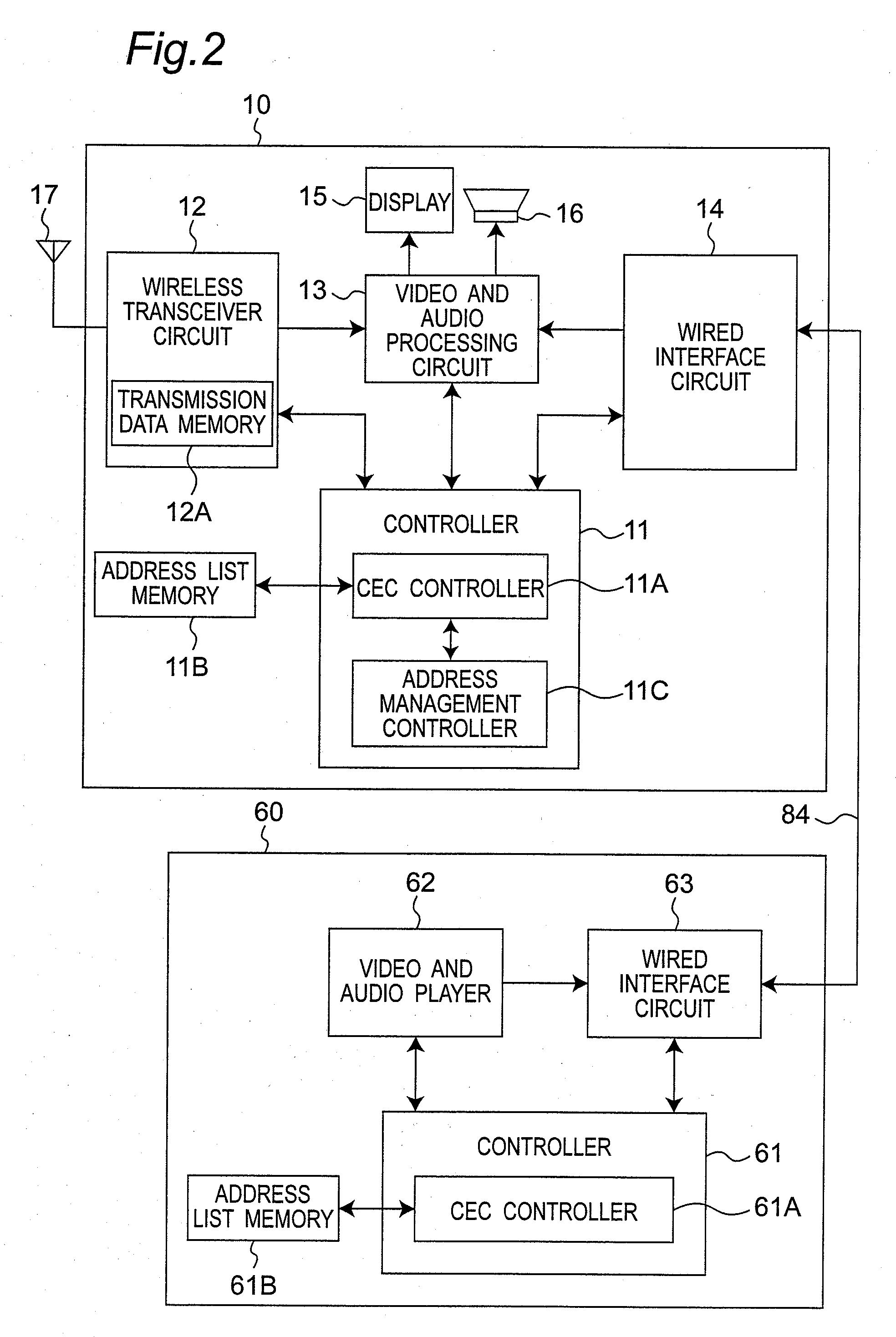
[0086]FIG. 1 is a block diagram showing an exemplary configuration of a wireless communication system according to a first preferred embodiment of the present invention, and FIGS. 2 to 4 are block diagrams showing detailed configurations of wireless node devices 10, 20, and 50 and wired node devices 30, 40, 70, and 60 of FIG. 1. Referring to FIGS. 1 to 4, the wired node devices 30, 40, 70, and 60 are configured as a device each provided with only a conventional HDMI wired interface, and the wireless node devices 10, 20, and 50 are configured as a device each provided with a wireless interface and a conventional HDMI wired interface. The wireless node device 20 is connected to the wired node device 30 through an HDMI cable 81, the wireless node device 20 is connected to the wired node device 40 through an HDMI cable 82, the wired node devices 30 is connected to the wired node devices 70 through an HDMI cable 83, and the wireless node device 10 is connected to the wired node device 60...
second preferred embodiment
[0130]A second preferred embodiment according to the present invention will be described below. The present embodiment is characterized in that, in addition to the configuration in the first preferred embodiment, a CEC controller 21A of a wireless node device 20 detects disconnection of another node device which has been connected by wire to the wireless node device 20, based on an HDMI 5V signal detected by a wired interface circuit 22. An address list table in an address list memory 21B further contains a physical address field, and a logical address is deleted from the address list table based on a 5V signal and a physical address. Explanations on the same features as those of the first preferred embodiment are omitted.
[0131]FIG. 15 is a flowchart showing a node device disconnection detecting process performed by the CEC controller 21A of the wireless node device 20 of FIG. 3, according to the second preferred embodiment of the present invention. In step S51 of FIG. 15, the CEC c...
PUM
 Abstract
Description
Claims
Application Information