Fuel-fired, power vented high efficiency water heater apparatus
a high-efficiency, water heater technology, applied in water heaters, water heaters, furnace-tube steam boilers, etc., can solve the problems of increasing the production cost of water heaters to an unacceptable extent, and reducing the overall energy efficiency of water heaters
- Summary
- Abstract
- Description
- Claims
- Application Information
AI Technical Summary
Benefits of technology
Problems solved by technology
Method used
Image

Examples
exemplary embodiment 292
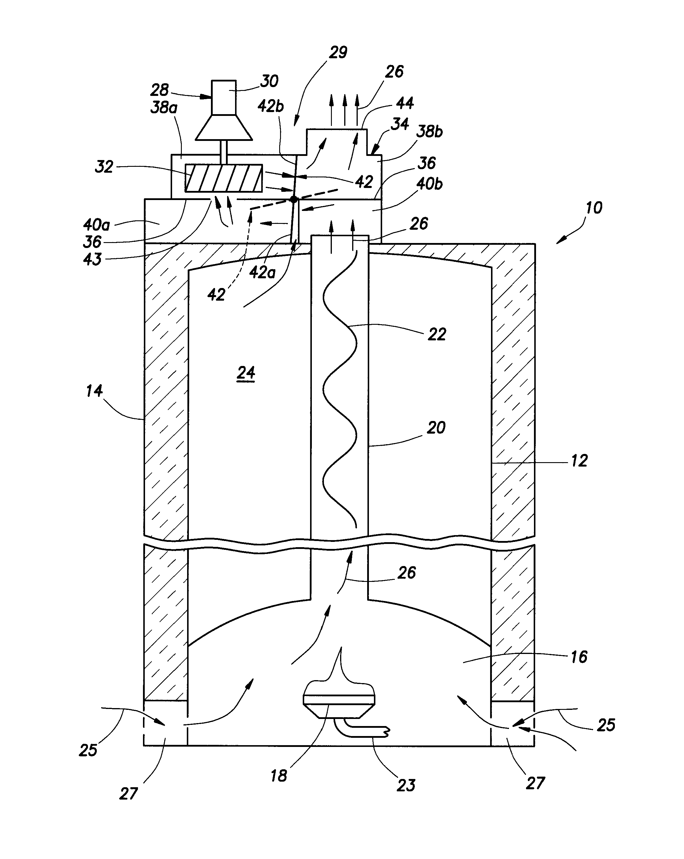
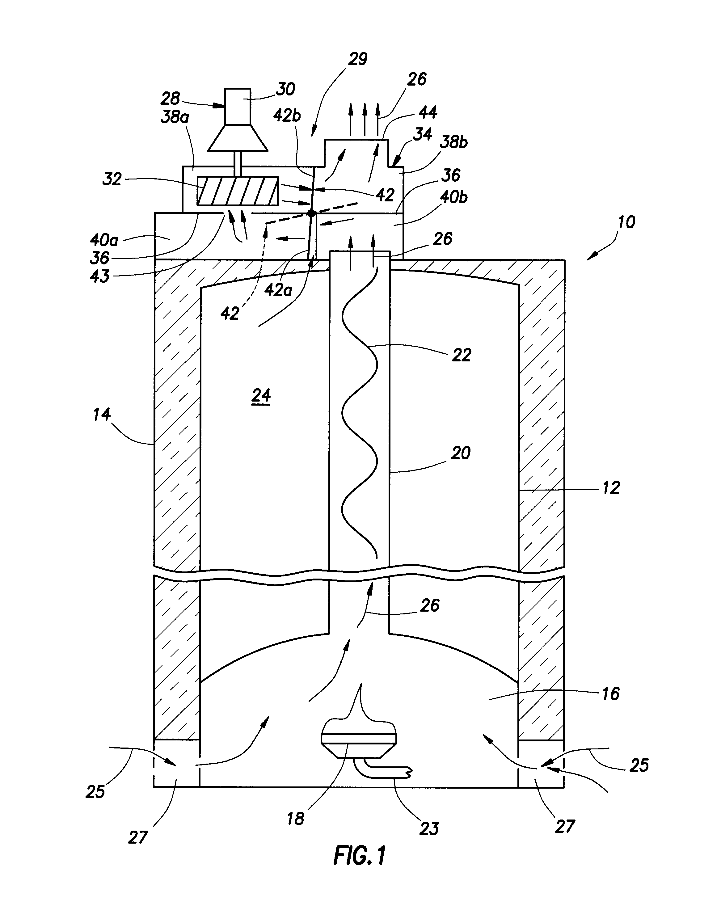
[0029]A second exemplary embodiment 292 of the previously described draft inducer fan assembly 29 is schematically shown in FIG. 2A. With the two exceptions noted below, the fan assembly 292 is identical to the previously described fan assembly 29. For ready comparison of the two fan assemblies 29 and 292, identical or substantially similar components in the two fan assembly embodiments have been given identical reference numerals.
[0030]The first difference between the fan assemblies 29 and 292 is that, in the fan assembly 292, during firing of the water heater 10, and operation of the draft inducer fan 28, ambient dilution air 61 is drawn into the housing subchamber 40a, via dilution air openings 63 in the side wall of the housing 34, for mixing with and cooling of the hot combustion products 26 entering the subchamber 38a via the opening 43. The second difference between the fan assemblies 29 and 292 is that in the assembly 292 the pressure tap 46 is relocated as shown in FIG. 2A....
exemplary embodiment 293
[0035]A third exemplary embodiment 293 of the previously described draft inducer fan assembly 29 is schematically shown in FIG. 7. With the exception noted below, the fan assembly 293 is identical to the previously described fan assembly 29. For ready comparison of the two fan assemblies 29 and 293, identical or substantially similar components in the two fan assembly embodiments have been given identical reference numerals.
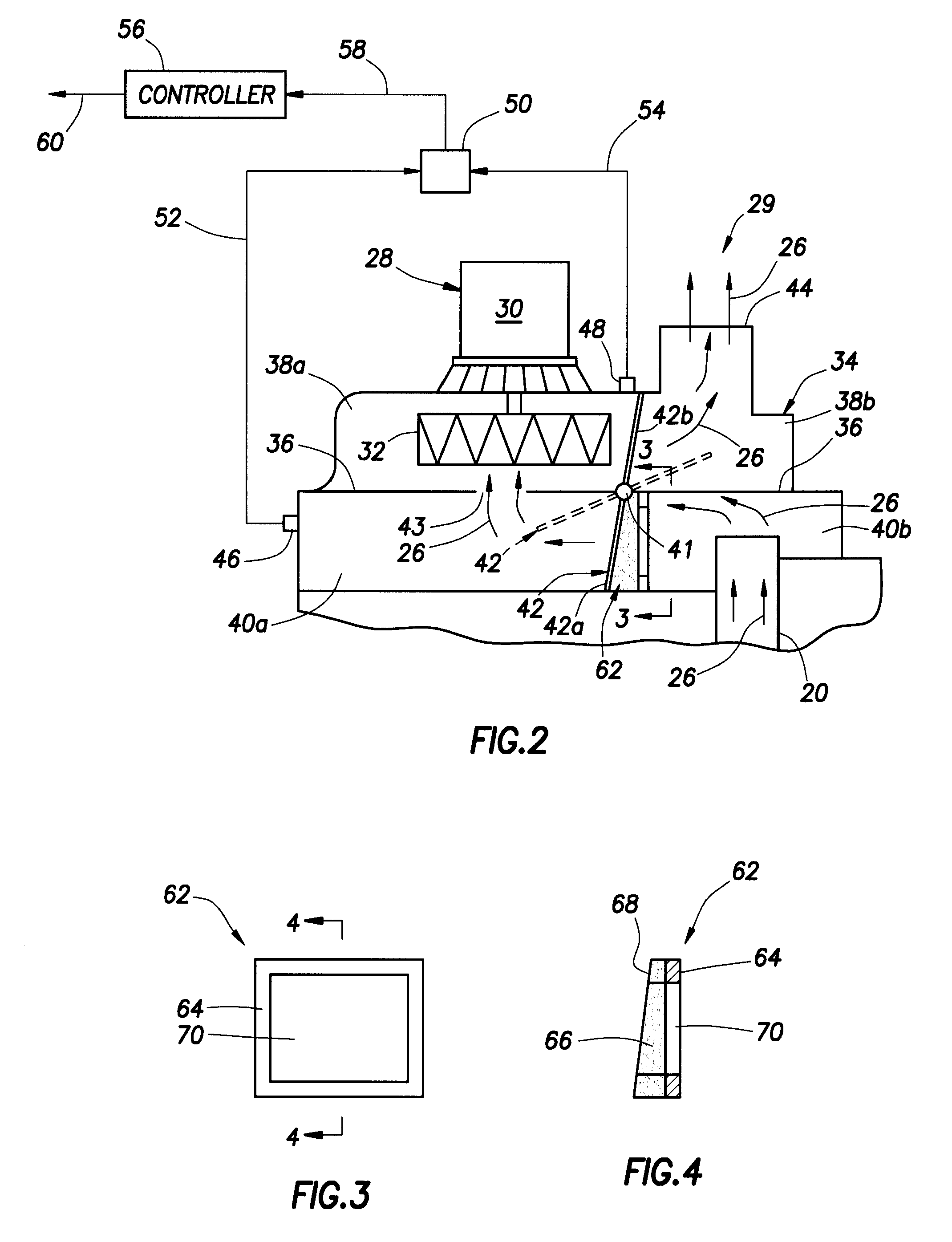
[0036]The difference between the fan assemblies 29 and 293 is that in the assembly 293 an additional damper stop / gasket structure 62 is operatively installed in the upper chamber 38 in a manner such that when the damper 42 is in its closed position its lower portion 42a sealingly engages the gasket material on the lower damper stop / gasket structure 62, and its upper portion 42b sealingly engages the gasket material on the upper damper stop / gasket structure 62. Thus, during standby periods of the water heater 10 undesirable upward convective heat flow from the flu...
exemplary embodiment 294
[0037]Schematically depicted in FIG. 8 is a fourth exemplary embodiment 294 of the previously described draft inducer fan assembly 29. Assembly 294 is operatively mounted on top of the previously described water heater 10, over the open upper end of its flue 20, and has a blower assembly housing 94 with an open bottom side that overlies the open upper end of the flue 20. Extending downwardly through a horizontally central portion of the assembly housing 94 into its interior is a fan impeller housing 96 in which the fan impeller 32 is rotatably disposed. As illustrated, the fan motor 30 is positioned to the right of the impeller housing 96 and is disposed within a dilution air receiving chamber portion 98 of the assembly housing 94.
[0038]A horizontal dividing wall 100 within the interior of the assembly housing 94 vertically divides a left interior portion thereof into a flue gas receiving chamber 102 disposed beneath the dividing wall 100, and a mixing chamber 104 disposed above the...
PUM
 Abstract
Description
Claims
Application Information
 - R&D
- Intellectual Property
- Life Sciences
- Materials
- Tech Scout
- Unparalleled Data Quality
- Higher Quality Content
- 60% Fewer Hallucinations
Browse by: Latest US Patents, China's latest patents, Technical Efficacy Thesaurus, Application Domain, Technology Topic, Popular Technical Reports.
© 2025 PatSnap. All rights reserved.Legal|Privacy policy|Modern Slavery Act Transparency Statement|Sitemap|About US| Contact US: help@patsnap.com