
Fluid treatment tank and a well fluid processing system comprising such a tank

Active Publication Date: 2009-08-27
SULZER MANAGEMENT AG
View PDF22 Cites 7 Cited by
  • Summary
  • Abstract
  • Description
  • Claims
  • Application Information

AI Technical Summary

Benefits of technology

[0009]Hereby, it will be possible to perform three different fluid treatment processes of a well fluid processing system in one and the same tank, which will save space and make possible a comparatively compact design of the system.
[0010]According to an embodiment of the invention, said compartments are mutually separated from each other in such a manner that fluid is allowed to flow from the upper part of the reject treatment compartment into the oil treatment compartment, but prevented from flowing from the upper part of the reject treatment compartment into the water treatment compartment. Hereby, oil accumulated in the upper layer of the fluid volume in the reject treatment compartment during the gravitational separation of the reject fluid will be allowed to flow over to the oil treatment compartment in order to form part of the export oil to be delivered from the oil treatment compartment. Thus, beneficial treatment of the reject fluid under utilization of the oil content thereof is made possible.
[0011]According to another embodiment of the invention, said compartments are also mutually separated from each other in such a manner that fluid is allowed to flow from the upper part of the water treatment compartment into the reject treatment compartment. Hereby, oil accumulated in the upper layer of the fluid volume in the water treatment compartment will be allowed to flow over to the reject treatment compartment so as to subsequently flow over to the oil treatment compartment from the reject treatment compartment. Thus, beneficial utilization of the oil content thereof is made possible.
[0014]According to another embodiment of the invention, the tank is provided with bubble producing means for producing gas bubbles in water introduced into or accumulated in the water treatment compartment so as to promote the flotation of oil droplets contained in water received in the water treatment compartment. Hereby, a further separation of oil from water in the water treatment compartment will be facilitated, which will make possible a reduction of the oil content of the water.
[0019]Hereby, a part of the water contained in reject fluid entering the reject treatment compartment via the inlet pipe will be discharged into the reject treatment compartment via said second outlet openings of the inlet pipe, whereas the major part of the lighter oil contained in said reject fluid will be discharged into the reject treatment compartment via said first outlet opening of the inlet pipe. Thus, an initial separation of oil and water of reject fluid may be accomplished as the reject fluid flows into the reject treatment compartment, which will speed up the separation process in the reject treatment compartment. The inlet pipe will also influence oil droplets of the reject fluid to form oil droplets of bigger size that will migrate easier to the surface of the fluid in the reject treatment compartment.
[0023]According to an embodiment of the invention, the system comprises a separation unit, which is arranged between the separator vessel and the water treatment unit and which is arranged to receive water withdrawn from the separator vessel. The separation unit comprises bubble producing means for producing micro-sized gas bubbles in said water, said gas bubbles being allowed to migrate through the water so as to come into contact with and carry along oil droplets included in the water, the separation unit further comprising an extraction device for withdrawing the gas bubbles and said oil droplets from the water in the separation unit so as to thereby reduce the oil content of the water passing through the separation unit. The water de-oiled by the separation unit is then supplied to the water treatment unit for further purification.

Problems solved by technology

This type of process is time-consuming and requires a very bulky separator installation.

Method used


Image

  • Fluid treatment tank and a well fluid processing system comprising such a tank
  • Fluid treatment tank and a well fluid processing system comprising such a tank
  • Fluid treatment tank and a well fluid processing system comprising such a tank

Examples


Embodiment Construction

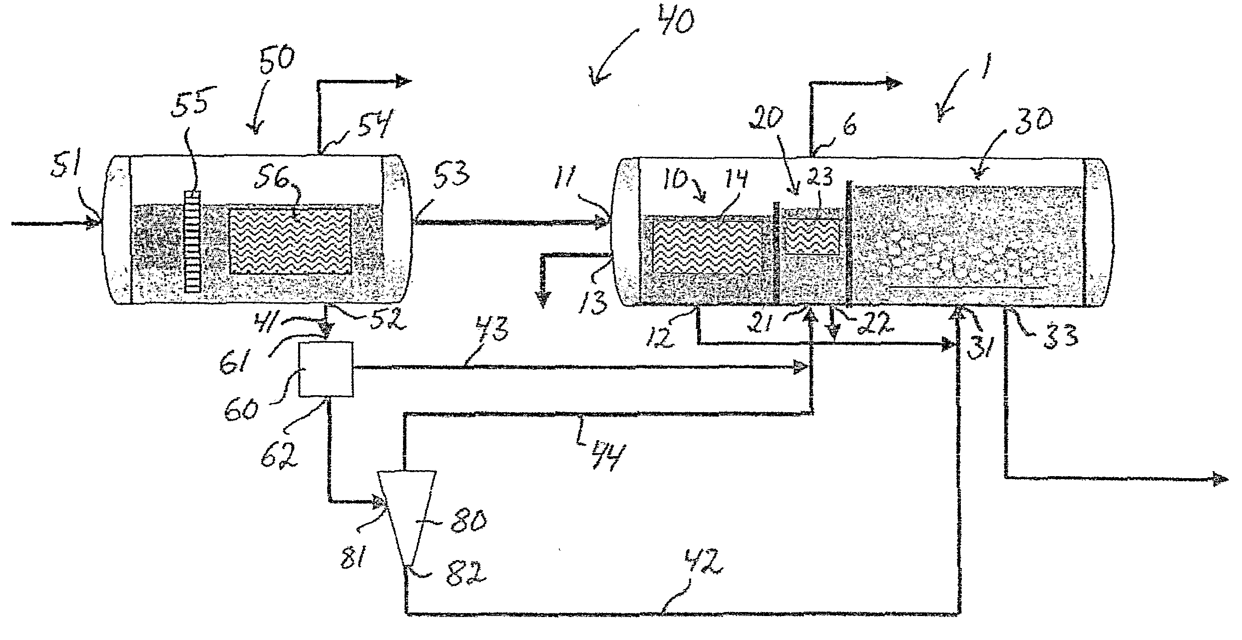
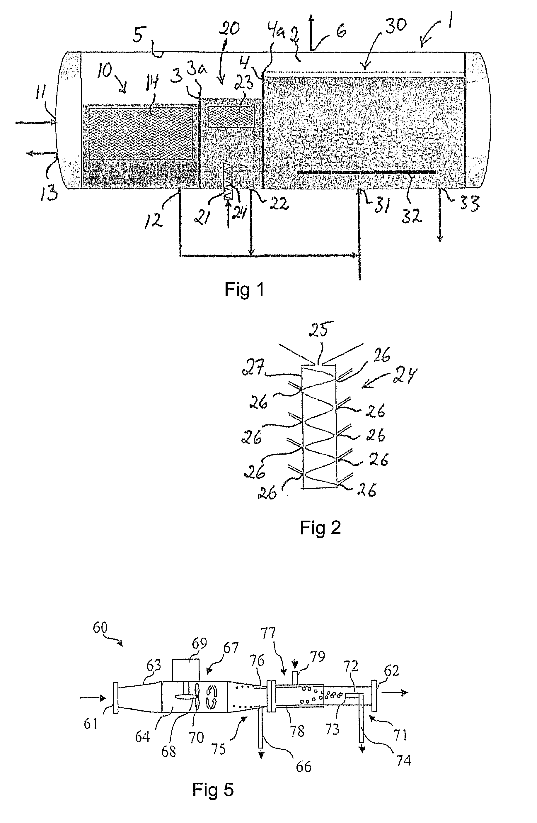
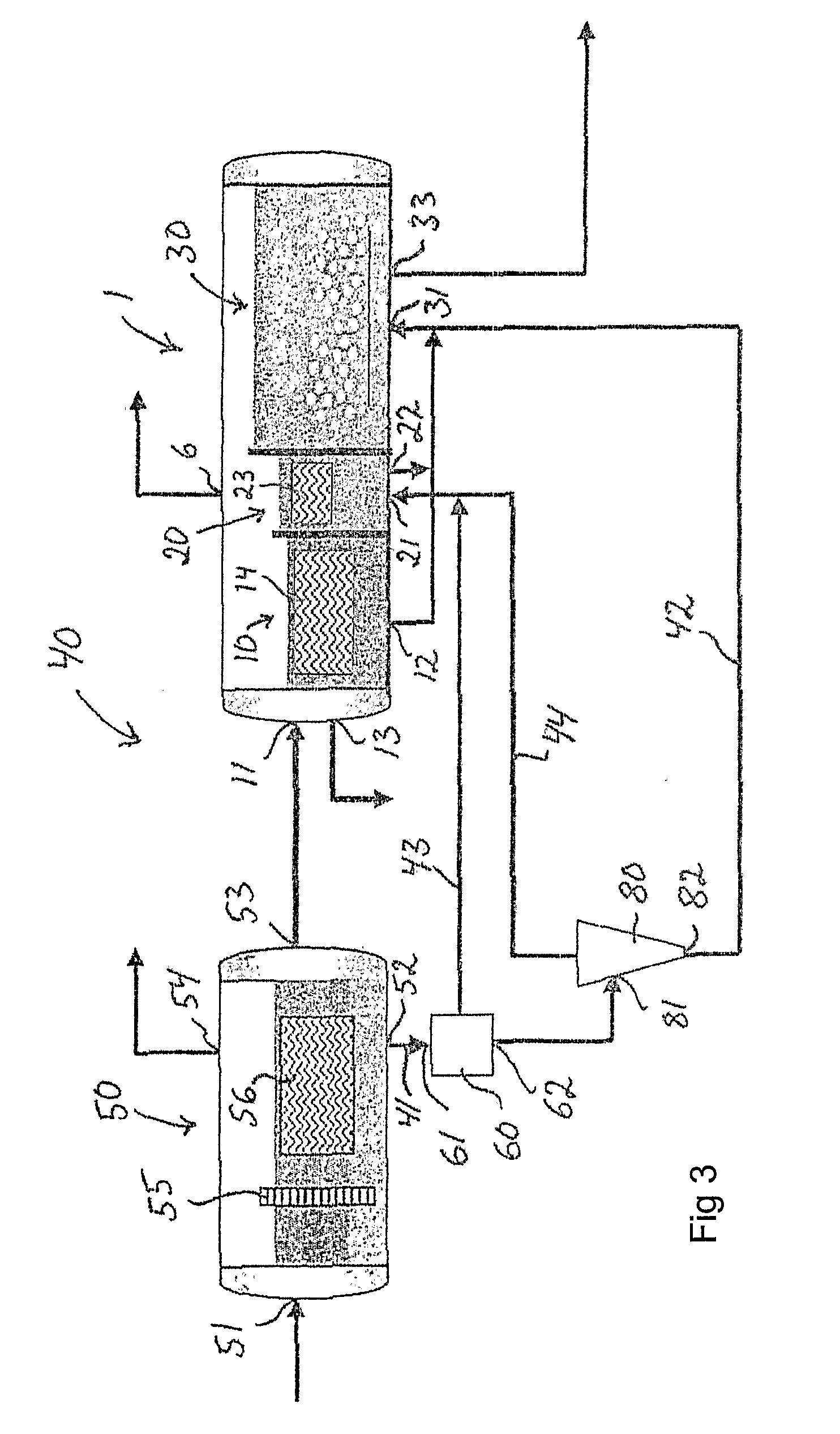
[0034]A fluid treatment tank 1 according to an embodiment of the present invention for use in a well fluid processing system is schematically illustrated in FIG. 1. In the illustrated embodiment, the tank 1 is divided into three compartments 10, 20, 30. Said compartments comprise:[0035]an oil treatment compartment 10 for receiving oil from a separator vessel of the well fluid processing system so as to allow final separation (such as polishing) and / or stabilization of the oil to a certain pressure and / or temperature;[0036]a reject treatment compartment 20 for receiving reject fluid from one or more water treatment units of the well fluid processing system so as to allow gravitational separation of heavier and lighter components of the reject fluid; and[0037]a water treatment compartment 30 for receiving de-oiled water from one or more water treatment units of the well fluid processing system so as to allow degassing and / or final separation (such as polishing) of the water.

[0038]The ...


PUM

PropertyMeasurementUnit
Pressureaaaaaaaaaa
Centrifugal forceaaaaaaaaaa
Contentaaaaaaaaaa

Abstract

A fluid treatment tank for use in a well fluid processing system. The tank is divided into at least three compartments, including an oil treatment compartment for receiving oil from a separator vessel of the well fluid processing system so as to allow stabilization and / or final separation and treatment of the oil, a reject treatment compartment for receiving reject fluid from one or more water treatment units of the well fluid processing system so as to allow gravitational separation of heavier and lighter components of the reject fluid, and a water treatment compartment for receiving de-oiled water from one or more water treatment units of the well fluid processing system so as to allow degassing and / or final separation of the water. Also, a well fluid processing system including such a fluid treatment tank.

Description

FIELD OF THE INVENTION AND PRIOR ART[0001]The present invention relates to a fluid treatment tank for use in a well fluid processing system. The invention also relates to a well fluid processing system comprising such a fluid treatment tank.[0002]Well fluid including a mixture of oil, water and gas is normally subjected to a three-stage gravitational separation process before oil of exportable quality, e.g. stabilized oil having a water content of 0.5% by volume or lower, is obtained. Each of said stages involves gravitational separation in a separator vessel, which implies that the oil has to pass through three separator vessels before being exported. This type of process is time-consuming and requires a very bulky separator installation. The water withdrawn from the respective separator vessel is conventionally subjected to purification in a water treatment unit such as a hydrocyclone, in which the oil content of the water may be reduced to such a low level that the water will be ...

Claims


Application Information

Patent Timeline
IPC IPC(8): E21B43/34B01D17/035B01D17/04B01D21/26B01D21/00B01D17/025
CPCB01D17/0205B01D19/0036E21B43/34B01D17/0217B01D17/0214B01D21/00B01D17/02
Inventor NILSEN, PAL JAHRECHIESA, MATTEOHANSSON, PEDERANDERSEN, HELGE L.
Owner SULZER MANAGEMENT AG
Features
  • Generate Ideas
  • Intellectual Property
  • Life Sciences
  • Materials
  • Tech Scout
  • Unparalleled Data Quality
  • Higher Quality Content
  • 60% Fewer Hallucinations
Learn More