Energy system

Active Publication Date: 2009-08-27
ABB (SCHWEIZ) AG
View PDF7 Cites 53 Cited by
  • Summary
  • Abstract
  • Description
  • Claims
  • Application Information

AI Technical Summary

Benefits of technology

[0006]An energy system of simple design is disclosed

Problems solved by technology

However, particularly in the case of wind energy systems which are installed off-shore in the sea, or in the case of tidal power energy systems which are typically installed under the water surface, a transformer, in particular oil transformers, is undesirab

Method used


Image

  • Energy system
  • Energy system
  • Energy system

Examples


Example

[0015]The reference symbols used in the drawing, and their meanings, are listed in a summarized form in the list of reference symbols. In principle, identical parts are provided with the same reference symbols in the figures. The described exemplary embodiments represent examples of the subject matter according to the disclosure, and have no restrictive effect.

DETAILED DESCRIPTION

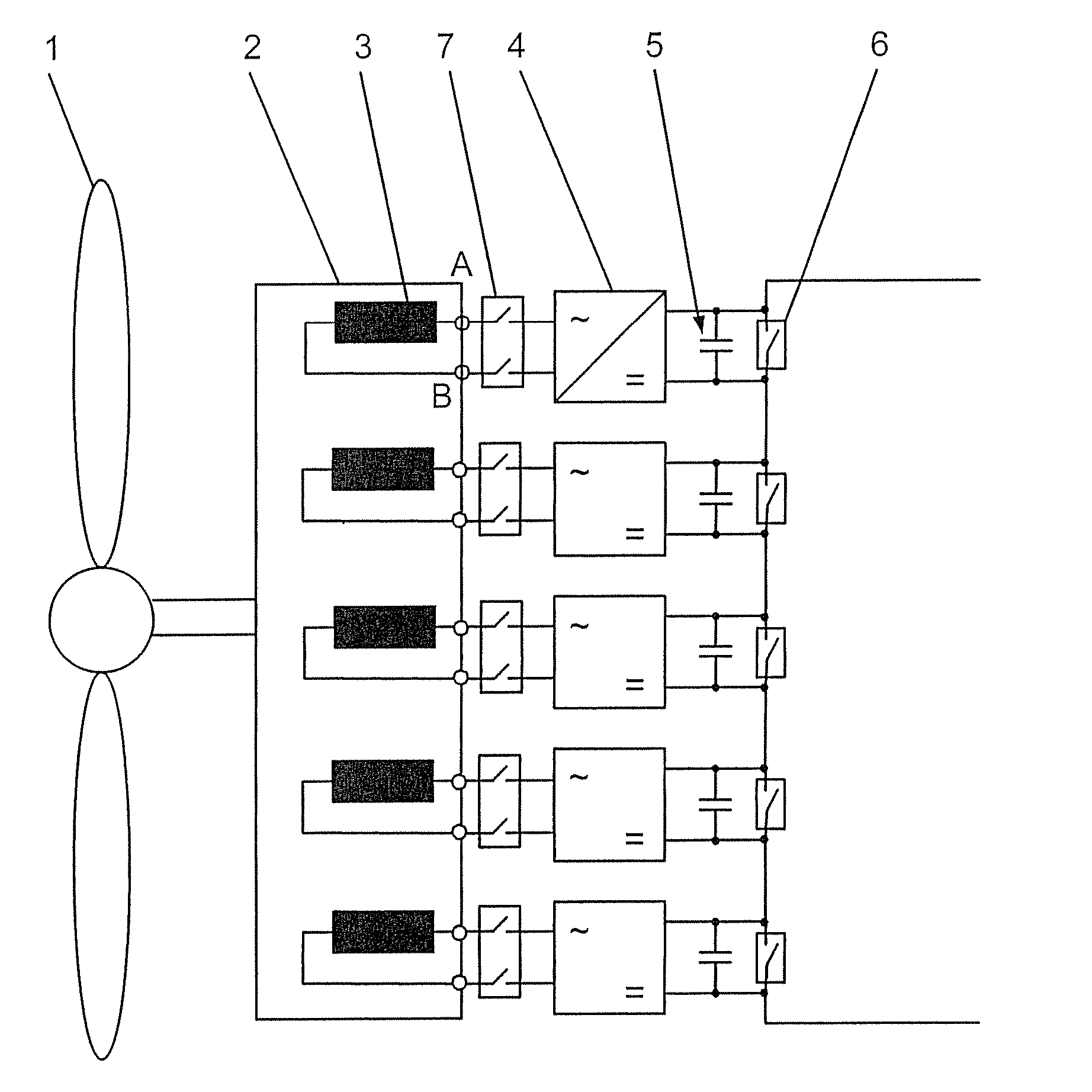
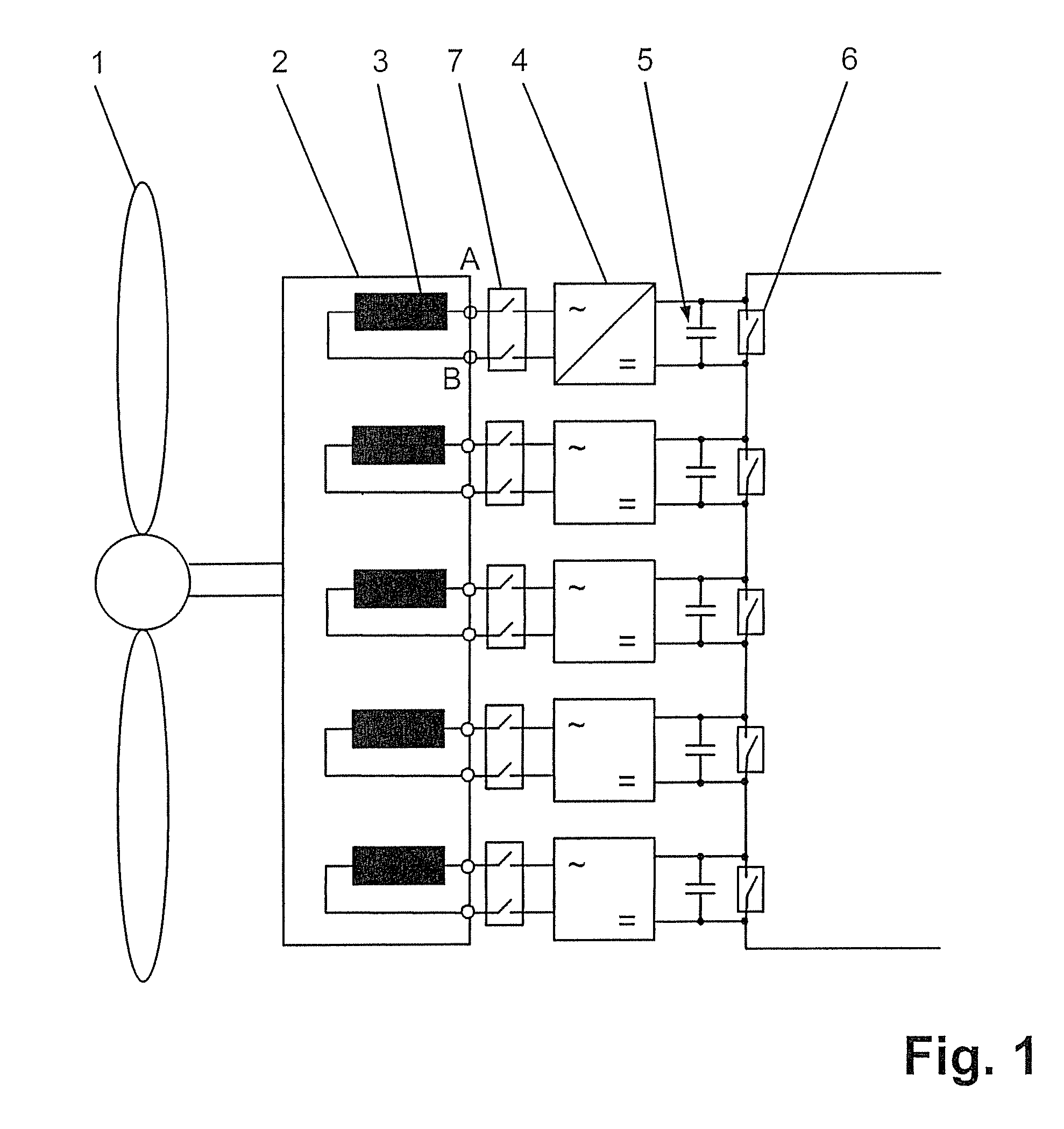
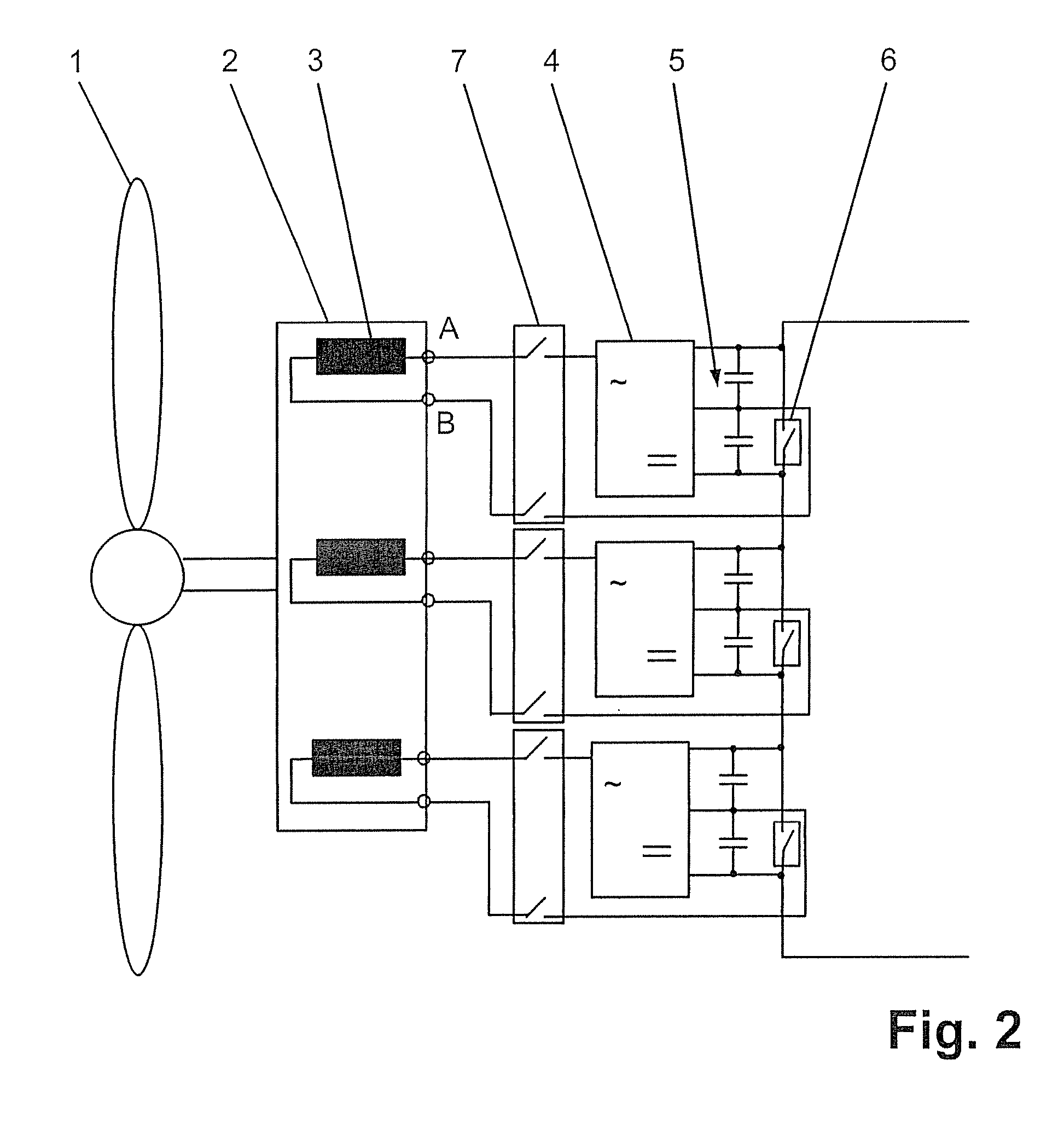
[0016]The energy system according to the disclosure comprises a wind power turbine or water power turbine, which is connected to a generator, with the generator having at least two stator windings. According to the disclosure, each stator winding now has a respectively associated rectifier unit, and each stator winding is connected to the AC voltage side of the associated rectifier unit. The number of rectifier units therefore corresponds to the number of stator windings. Furthermore, each rectifier unit has a respective associated energy storage circuit, and each rectifier unit is connected in parallel on ...


PUM


Abstract

An energy system is specified, which comprises a wind power turbine or water power turbine, which is connected to a generator, with the generator having at least two stator windings. In order to achieve a simple and robust design without a transformer, each stator winding has an associated rectifier unit, and each stator winding is connected to the AC voltage side of the associated rectifier unit. Furthermore, each rectifier unit has a respective associated energy storage circuit, and each rectifier unit is connected in parallel on the DC voltage side to the associated energy storage circuit, with the energy storage circuits being connected to one another in series.

Description

RELATED APPLICATION[0001]This application claims priority under 35 U.S.C. §119 to European Patent Application No. 08152006.6 filed in Europe on Feb. 27, 2008, the entire content of which is hereby incorporated by reference in its entirety.TECHNICAL FIELD[0002]The disclosure relates to the field of renewable energies and is based on an energy system.BACKGROUND INFORMATION[0003]Wind energy systems, as are now being increasingly used as alternative energy supplies as a result of disappearing energy resources, are conventionally installed on land or in the sea close to the coast. Tidal power energy systems are in turn typically installed on the seabed, while the tidal range or the flow of the sea water is used as the primary energy source.[0004]A wind energy system of this generic type is specified in “Power Quality Measurements Performed on a Large Wind Park at Low and Medium Voltage Level”, E. Ghiani et al., International Conference on Power System Transients, Jun. 4-7, 2007. In this ...

Claims


Application Information

Patent Timeline
IPC IPC(8): F03D9/00
CPCF03D9/002H02J3/28H02K7/1823H02K7/183H02K11/046Y02E10/725H02K19/34Y02E10/766Y02E70/30H02K7/1838H02J3/386H02J3/382H02K21/48Y02E10/763F03D9/25F03D9/008F03D9/11H02J2300/28H02J2300/20H02J3/381Y02E10/76Y02E10/72H02M7/00
Inventor MAIBACH, PHILIPPEEICHLER, MARKUSSTEIMER, PETER
Owner ABB (SCHWEIZ) AG
Why Eureka
Try Eureka