
Panoramic camera

a technology of panoramic camera and panoramic lens, which is applied in the field of surveillance systems, can solve the problems that the artificial light source cannot omit sufficient ultraviolet light to trigger the photochromic effect, and cannot invoke the desired photochromic

Inactive Publication Date: 2009-08-27
GLATT OTTO GREGORY
View PDF6 Cites 117 Cited by
  • Summary
  • Abstract
  • Description
  • Claims
  • Application Information

AI Technical Summary

Benefits of technology

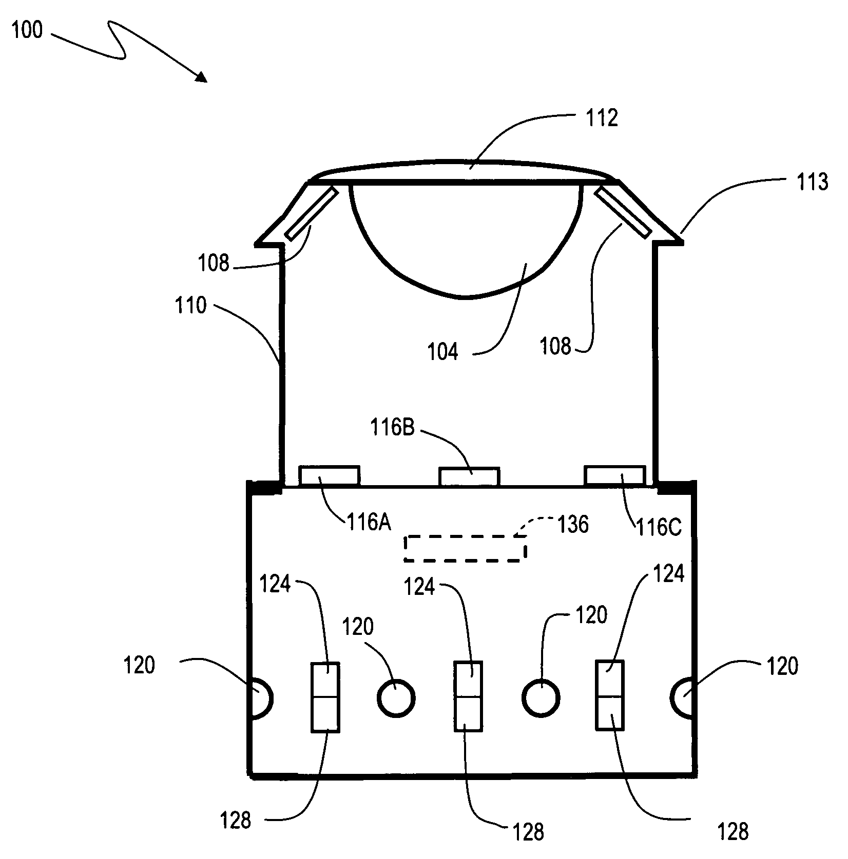
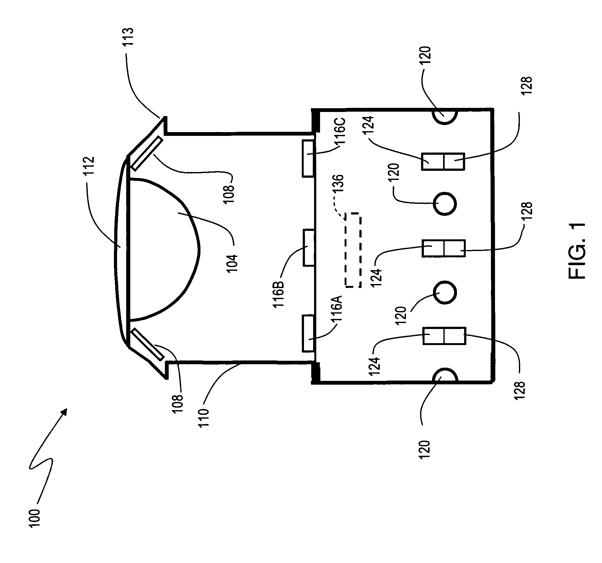
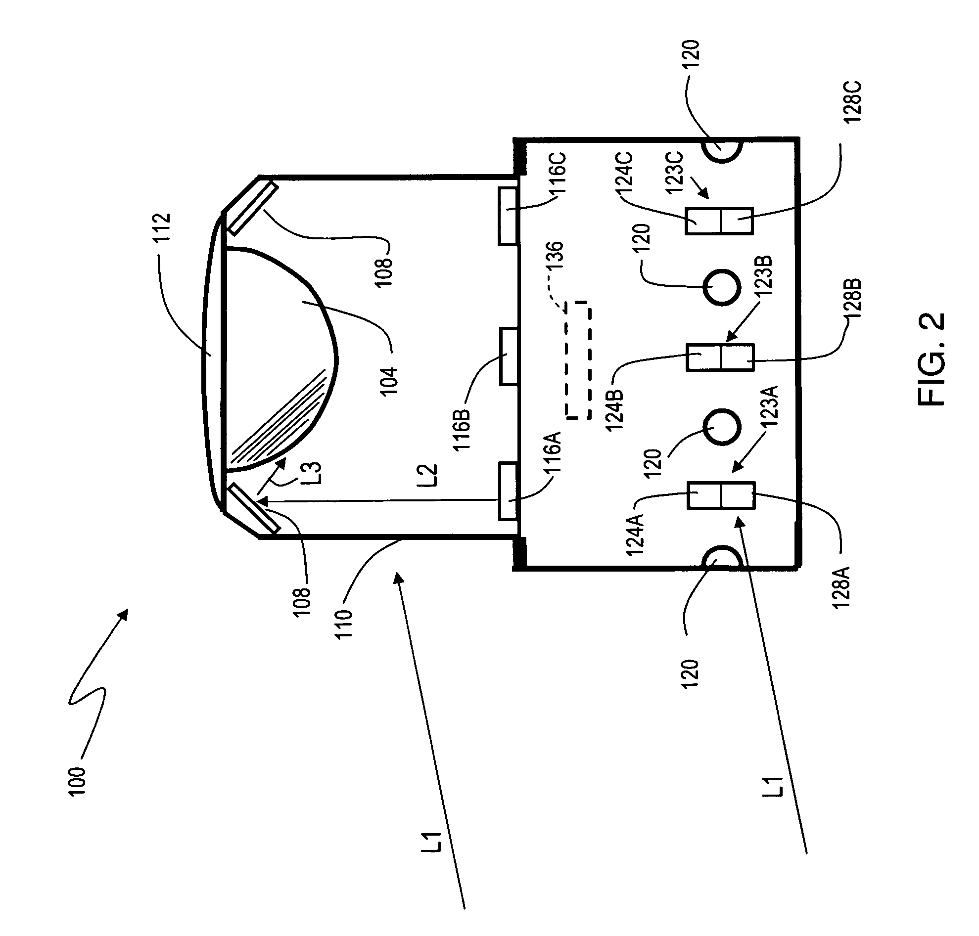
[0004]The present invention provides for an improved camera for the acquisition of 360 degree panoramic images. The camera comprises a convex photochromic reflector disposed at one end of a generally cylindrical housing. The photochromic reflector is directed towards an image capture element (such as a CCD array) at the other end of the housing. The photochromic reflector darkens when exposed to light in the ultraviolet range. For example, sunlight during times where the sun is low in the sky (e.g. early morning or late afternoon) causes the photochromic reflector to darken in the area where the sunlight illuminates the reflector. On the opposite side, not exposed to sun, the photochromic effect does not substantially darken the reflector on that side. The net effect is to direct a light-compensated image into the image capture element.
[0006]To accommodate these situations, the present invention provides a plurality of UV lights disposed around the photochromic reflector. There are also multiple light sensors around the exterior of the camera. When a light sensor detects light above a predetermined intensity level, the corresponding UV light is activated. This causes the photochromic effect to occur in the area where the incident light is received, and creates the desired photochromic effect in that area. A radial mirror (a mirror in the form of a ring that goes around the reflector, and is angled towards the reflector) serves to direct as much of the UV light as possible onto the photochromic reflector, to help maximize the photochromic effect. Therefore, the camera compensates for strong lighting indoors as well as outdoors.
[0008]To provide for additional darkening, the housing may also be comprised of a photochromic material. In this embodiment, there is a “double” photochromic effect, from both the housing and the reflector. This provides for more compensation in extra bright situations.
[0009]In another embodiment, heating elements are disposed to prevent icing of the camera during cold weather operations. In yet another embodiment, a dew point temperature is calculated from temperature, humidity, and barometric pressure sensors that are on the camera housing. The heating elements are activated to warm the photochromic housing and photochromic reflector when the ambient temperature falls below a predetermined value (e.g. freezing temperature, or a calculated dew point temperature). This maintains the camera temperature above the dew point temperature, and avoids condensation on the optical components such as the reflector or housing.

Problems solved by technology

However, indoors, an artificial light source may not omit sufficient UV light to trigger the photochromic effect.
Furthermore, many home and building windows filter out substantial UV light.
In the case of a 360 degree security camera mounted indoors, yet near a window, it is possible that ambient sunlight may enter the camera, yet the UV components may be filtered out, and therefore does not invoke the desired photochromic effect.

Method used


Image

  • Panoramic camera
  • Panoramic camera
  • Panoramic camera

Examples


Embodiment Construction

[0021]FIG. 1 and FIG. 2 show a side view of a camera 100 in accordance with an embodiment of the present invention. The camera 100 comprises an optical housing 110 that is substantially transparent. A photochromic reflector 104 is disposed at the top of the housing, and configured to reflect the light from a 360 degree field of view around the camera to an image capture element 136 located within the base of the camera. Top cover 112 provides an overhang 113 that extends beyond the circumference of the optical housing 110 and circumscribes it, so as to block the overhead sun's rays from going directly into the camera. Radial mirror 108 serves to direct UV light from light sources 116 onto the reflector 104.

[0022]Around the exterior of camera 100 are a plurality of UV (ultraviolet) lights 116A-116C that are directed at photochromic reflector 104. This enables the photochromic reflector 104 to be darkened in a particular direction as needed, providing additional control of the photoch...


PUM


Abstract

An improved camera for the acquisition of panoramic images is disclosed. The camera comprises a convex photochromic reflector directed towards an image capture element. Multiple incoming light sensors around the perimeter of the camera detect strong incoming light and cause the activation of a corresponding UV light. The UV light in turn activates the photochromic effect on a particular region of the photochromic reflector that corresponds to an area of strong incident light. The photochromic reflector then darkens in that area, providing compensation for a scene that has a wide range of lighting conditions. Therefore, the camera compensates for strong lighting indoors as well as outdoors.

Description

CROSS-REFERENCE TO RELATED APPLICATIONS[0001]This application is a continuation-in-part of U.S. patent application Ser. No. 12 / 035,404 (Panoramic Image Management System and Method), filed on Feb. 21, 2008.FIELD OF THE INVENTION[0002]The present invention generally pertains to surveillance systems. More particularly, the present invention pertains to imaging systems for the panoramic surveillance of a space using a single, stationary camera.BACKGROUND[0003]Panoramic cameras provide a convenient way to capture a 360 degree field of view with a single camera. Cameras of this type are very useful for surveillance and security applications. Such systems are disclosed in U.S. Pat. No. 7,071,964 (360-Degree Panoramic Scene-Storage Device), and U.S. patent application Ser. No. 12 / 035,404 (Panoramic Image Management System and Method). Both of these references are incorporated herein by reference, to the extent not inconsistent with this disclosure. Exposure control with cameras of this typ...

Claims


Application Information

Patent Timeline
Patent Type & Authority Applications(United States)
IPC IPC(8): H04N7/00
CPCG03B37/00G08B13/19628H04N5/332H04N5/2256H04N5/23238H04N5/2252H04N23/56H04N23/51H04N23/698H04N23/11
Inventor GLATT, OTTO
Owner GLATT OTTO GREGORY
Learn More