Method and apparatus for projection printing

a technology of projection printing and projection, applied in the direction of photomechanical treatment, printers, instruments, etc., can solve the problem of discontinuity in functions, and achieve the effect of improving the performance of such patterns, the time it takes, and high resolution and fidelity

Inactive Publication Date: 2009-08-27
MICRONIC LASER SYST AB
View PDF9 Cites 14 Cited by
  • Summary
  • Abstract
  • Description
  • Claims
  • Application Information

AI Technical Summary

Benefits of technology

[0009]We disclose a method to project an optical image onto a workpiece with extremely high resolution and fidelity, given the constraints of optical components. Particular aspects of the present invention are described in the

Problems solved by technology

However, due to manufacturing and design restrict

Method used


Image

  • Method and apparatus for projection printing
  • Method and apparatus for projection printing
  • Method and apparatus for projection printing

Examples


Embodiment Construction

[0045]The following detailed description is made with reference to the figures. Preferred embodiments are described to illustrate the present invention, not to limit its scope, which is defined by the claims. Those of ordinary skill in the art will recognize a variety of equivalent variations on the description that follows.

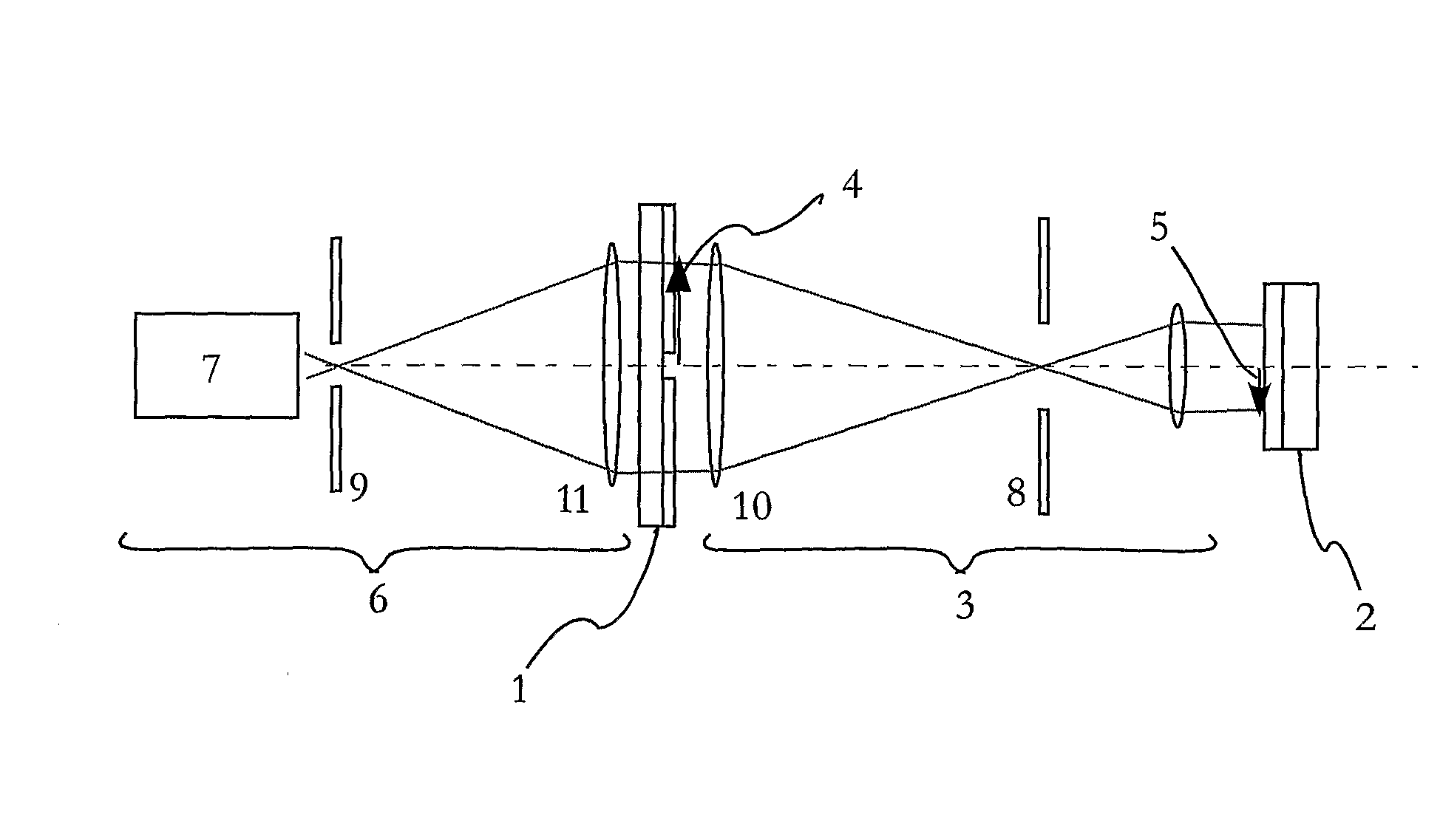
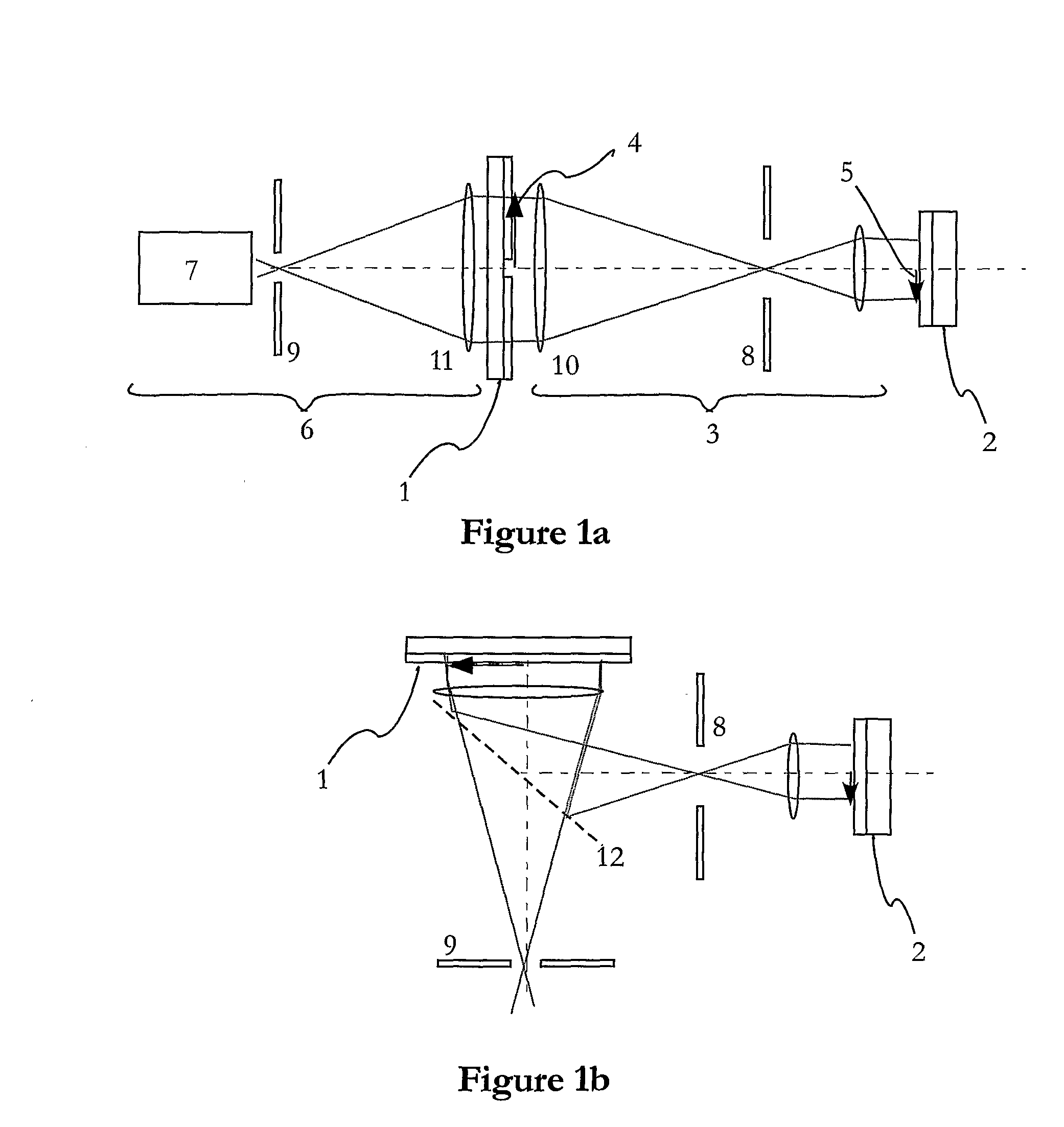
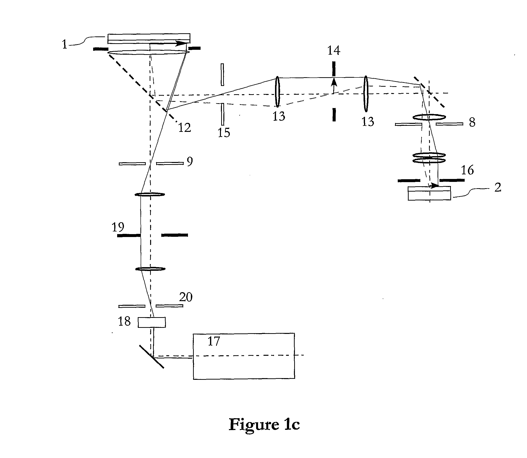
[0046]A generic projection system has been defined in FIG. 1a. It has an object 1, which can be a mask or one or several SLMs, and a workpiece 2, e.g. a mask blank, a wafer or a display device. Between them is a projection system 3 creating an image 5 of the image 4 on the object. The object is illuminated by an illuminator 6. The projection system consists of one or several lenses (shown) or curved mirrors. The NA of the projection system is determined by the size of the pupil 8. The illuminator 6 consists of an essentially non-coherent light source 7 illuminating the illumination aperture 9. Field lenses 10 and 11 are shown but the presence of field lenses is n...


PUM


Abstract

A method, apparatus for and a device manufactured by the same, for printing a microlithographic pattern with high fidelity and resolution using simultaneously optimized illuminator and pupil filters having semi-continuous transmission profiles. The optimization can be further improved if the illuminator and pupil filters are polarization selective. The optimization method becomes a linear programming problem and uses a set of relevant features in the merit function. With a suitably chosen merit function and a representative feature set both neutral printing without long-range proximity effects and good resolution of small features can be achieved. With only short-range proximity effects OPC correction is simple and can be done in real time using a perturbation method.

Description

PRIORITY INFORMATION[0001]This application claims the benefit of U.S. Provisional Application No. 60 / 706,550, entitled “Method and Apparatus for Projection Printing” filed on 8 Aug. 2005 by Igor Ivonin and Torbjorn Sandstrom.FIELD OF THE INVENTION[0002]The present invention teaches a method to project an optical image of an original (typically a pattern on a photomask or a spatial light modulator (SLM)) onto a workpiece with extremely high resolution and fidelity given the constraints of the optics. Used with masks, it allows the mask to use less so called optical proximity correction (OPC), which pre-distorts or pre-adjusts a pattern to correct for optical deterioration that is normally found near the resolution limit. Therefore, patterns can be printed with the invention down to the resolution limit with high fidelity and only simple OPC processing or no OPC processing at all. With spatial light modulators (SLMs) as the image source, e.g. in mask pattern generators and direct-writ...

Claims


Application Information

Patent Timeline
IPC IPC(8): G03B27/72G03B27/32
CPCG03F7/701G03F7/70566G03F7/70308G03F7/70291
Inventor SANDSTROM, TORBJORNIVONIN, IGOR
Owner MICRONIC LASER SYST AB
Why Eureka
Try Eureka